The premiere source of truth powering network automation. Open and extensible, trusted by thousands.
NetBox is now available as a managed cloud solution! Stop worrying about your tooling and get back to building networks.
Networking FAQ 4: Fundamentals
By stretch | Monday, January 26, 2015 at 2:50 p.m. UTC
- At what OSI layer does protocol X operate?
- What's the difference between a router and a multilayer switch?
- What's the difference between forwarding and control planes?
- What's the difference between MTU and MSS?
- What's the difference between a VLAN interface and a BVI?
- How do tunnel interfaces work?
- What do NAT terms like "inside local" mean?
- Can I use the network and broadcast addresses in a NAT pool?
- Why do we need IP addresses? Can't we just use MAC addresses for everything?
- Does QoS provide more bandwidth?
At what OSI layer does protocol X operate?
The Open Systems Interconnection (OSI) model is one of the first things you learn about networking. It's a seven-layer reference model officially defined in ISO/IEC 7498-1 and reprinted in every certification study book ever published. It serves as a common point of reference when discussing how protocols relate to and inter-operate with one another. For example, we know that TCP is a layer four protocol, and therefore it sits "on top of" IP, which is a layer three protocol.
But what does that really mean? Who decides what layer a protocol belongs to? The OSI model was originally conceived back in the 1970s as a component of the OSI protocol suite, which was positioned as an early competitor to the emerging TCP/IP family of protocols (spoiler alert: TCP/IP won.) Except for a handful of survivors (most notably the IS-IS dynamic routing protocol) OSI protocols are not in common use today. The reference model which was to govern how these protocols operated, however, lives on. So, we end up trying to assign protocols from one family to layers originally defined for another.
For the most part, this works out alright. TCP and UDP ride on top of IP, which rides on top of Ethernet or PPP or whatever. But protocols don't always fit the mold: MPLS, for example, is sometimes referred to as "layer 2.5" since it neither provides framing nor provides end-to-end addressability. (Unlike IP addresses, MPLS labels are swapped at each hop along a path as a packet transits a network.) Of course, inventing a layer between two other layers defeats the purpose of a standardized reference model in the first place, and just belies how dependent some people are on reducing every logical concept to a number.
Technically speaking, no protocol from the TCP/IP stack has an official assignment to an OSI layer, because they're not of the same family. Apples and oranges. A reference model is just that: a reference. It helps illustrate the dependencies protocols have on another, and where they sit in relation to one another, but it doesn't strictly govern their function. To give the concept any more weight than that is to miss its purpose entirely.
But if anyone asks, MPLS is a layer three protocol.
What's the difference between a router and a multilayer switch?
Back in simpler times, a router was a device that forwarded packets based on their IP addresses and offered a variety of interface types: Ethernet, T1, serial, OC-3, and others. Conversely, a switch was a device which forwarded packets (or frames, if you prefer) based on their MAC addresses and included only Ethernet ports.
Since the early 2000s the industry has seen two major trends which have greatly upset this understanding. First, the introduction of the multilayer switch meant it was possible for a switch not only to forward packets based on IP addresses, but to participate in dynamic routing protocols just like a router. Second, carriers began migrating away from legacy long-haul circuit technologies in favor of Ethernet for its speed and lower cost. In fact it's fairly common for routers today to consist entirely of Ethernet interfaces, just like their switch counterparts.
So where do we draw the line? Is there even a line anymore? The practical distinction between router and switch boils down to a few key functions:
-
Port density. Enterprise-level switches typically come in 24- and 48-port variants, either as standalone devices or as modular chassis. Some are designed as separate physical chassis which can be stacked via a flexible external backplane connection. The goal is to fit as many physical interfaces in as dense a space as possible. A router, by contrast, might have have far fewer individual interfaces split across several field-replaceable modules.
-
Speed. Switches are built primarily for speed, which is a function of the hardware chipset sitting behind the ports. It is common for even modest access switches today to support non-blocking line-rate connectivity.
-
Intelligence. This is the key reason you might need a router instead of a switch. A router serves as a point of intelligent policy enforcement. This includes functions like network address translation, deep packet inspection (looking beyond the outer protocol headers), stateful firewalling, encryption, and similar more involved operations not supported on a multilayer switch.
That's the current theory regarding purpose-built hardware, anyway. With the current push toward virtual appliances, commodity hardware is being re-purposed for a variety of roles.
What's the difference between forwarding and control planes?
This is a source of much confusion for people new to networking. Simply put, the forwarding plane handles moving a packet from point A to point B. The control plane handles functions which determine how the forwarding plane operates.
Let's say you've got a router running OSPF. It exchanges routes with neighboring OSPF routers and builds a table of all the routes on the network. Once the routing table has been built, the router installs the best route for each known destination into its forwarding table. This is a control plane function.
When the router receives an IP packet on an interface, it looks up the destination address of that packet in its forwarding table to determine out which interface the packet should be sent. The packet is then moved in memory to the output buffer of that interface and transmitted onto the wire. This is a forwarding plane function.
See the difference? The forwarding plane handles the reception and transmission of packets, whereas the control plane governs how forwarding decisions are made. Forwarding plane operations are typically done "in hardware," which is to say they are performed by specialized chipsets requiring little interaction with the device's general-purpose CPU. Control plane functions, on the other hand, are handled in software by CPU and memory very similar to what's in your personal computer. This is because control protocols perform very complex functions which don't usually need to occur in real-time. For example, it's usually not a big deal if there's a delay of several milliseconds before installing a new route in the forwarding table. Such a delay could be devastating for the performance of the forwarding plane, however.
What's the difference between MTU and MSS?
The maximum transmission unit (MTU) of a network protocol dictates the maximum amount of data that can be carried by a single packet. Usually when we talk about MTU we're referring to Ethernet (although other protocols have their own MTUs). The default Ethernet MTU for most platforms is 1500 bytes. This means that a host can transmit a frame carrying up to 1500 bytes of payload data, which does not include the 14-byte Ethernet header (or 18 bytes if tagged with IEEE 802.1Q) or 4-byte trailer, resulting in a total frame size of 1518 bytes (or 1522 bytes with IEEE 802.1Q). Many network devices support jumbo frames by way of increasing the default MTU as high as 9216 bytes, but this is administratively configurable.
Maximum segment size (MSS) is a measure specific to TCP. It indicates the maximum TCP payload of a packet; essentially it is the MTU for TCP. The TCP MSS is calculated by an operating system based on the Ethernet MTU (or other lower layer protocol MTU) of an interface. Because TCP segments must fit within Ethernet frames, the MSS should always be less than the frame MTU. Ideally, the MSS should be as large as possible after accounting for the IP and TCP headers.
Assuming an Ethernet MTU of 1500 bytes, we can subtract the IPv4 header (20 bytes) and TCP header (another 20 bytes) to arrive at an MSS of 1460 bytes. IPv6, with its longer 40-byte header, would allow an MSS of up to 1440 bytes.
TCP MSS is negotiated once at the initiation of a session. Each host includes its MSS value as a TCP option with its first packet (the one with the SYN flag set), and both hosts select the lower of the two MSS values as the session MSS. Once selected, the MSS does not change for the life of the session.
What's the difference between a VLAN interface and a BVI?
A VLAN interface, also referred to as a switch virtual interface (SVI) or routed VLAN interface (RVI) is a virtual interface created on a multilayer switch to serve as the routed interface for a VLAN, often to provide a default gateway out of the local subnet. VLAN interfaces typically operate and are configured the same as physical routed interfaces: They can be assigned IP addresses, participate in VRRP, have ACLs applied, and so on. You can think of it as a physical interface inside the switch that's assigned to a VLAN just like one of the physical ports on the outside of the switch.
A bridge group virtual interface (BVI) serves a similar function, but exists on a router where there is no concept of a VLAN (because all its ports normally function at layer three) instead of a switch. A bridge group is a set of two or more physical interfaces operating at layer two, with all member interfaces sharing a common broadcast domain. The BVI is tied to a bridge group to serve as a single virtual layer three interface for all segments connected to the bridge group. When a router has interfaces operating at both layers two and three it is referred to as integrated routing and bridging (IRB).
While VLAN interfaces are a necessity of multilayer switching, IRB is typically used only in niche designs which call for a layer two domain to span multiple router interfaces, such as on a wireless access point.
How do tunnel interfaces work?
A lot of people struggle to understand the concept behind tunnel interfaces. Remember that a tunnel is just the effect of encapsulating one packet inside another as it passes between two points. Tunnel interfaces are used to achieve this encapsulation for route-based VPNs, which can provide a layer of security or abstraction from the underlying network topology. There are a number of encapsulation methods available, including IPsec, GRE, or just plain IP-in-IP.
Although tunnel interfaces are virtual in nature, they behave just like any other interface when it comes to routing decisions. When a packet is routed "out" a tunnel interface, it is encapsulated and a second routing decision is made based on the new (outer) header. This new packet is then forwarded across the wire to another device. Eventually, the packet reaches the far tunnel endpoint, where its outer header is stripped away. A routing decision is made on the original inner packet, which can be forwarded on to its destination in its original form.
For more detail on the whole process, check out Visualizing Tunnels.
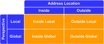
What do NAT terms like "inside local" mean?
An IP address within the context of NAT can be considered one of these four classes:
- Inside global
- Inside local
- Outside local
- Outside global
Unfortunately, these terms are rarely explained in documentation to the satisfaction of the reader. Each term describes two separate attributes of the address: location and perspective. Location is described by the first word in the tuple, either inside or outside. It refers to the "side" of the NAT boundary router in which the address logically exists. In a typical NAT deployment, inside addresses will usually (but not necessarily) be private RFC 1918 addresses, and outside addresses will usually be globally routable (public) IP addresses.
Perspective refers to the side of the NAT boundary from which the address is observed: local or global. If an address is seen by an inside host, it is being observed locally. If an address is seen by an outside host, it is observed globally.
If the terms are still foggy, check out this article on NAT types for a simple example.
Can I use the network and broadcast addresses in a NAT pool?
Yes! Many people assume that because the network and broadcast addresses of a subnet are unusable for host addressing, they cannot be used in a NAT pool. However, a NAT pool has no concept of a subnet mask: This is why you can define NAT pools using arbitrary ranges that don't conform to binary boundaries (for example, 192.168.0.10 through 192.168.0.20). This includes the IPs which would be designated as the network or broadcast address of a "real" subnet.
Why do we need IP addresses? Can't we just use MAC addresses for everything?
When you first learned that MAC addresses were intended to be globally unique, you might have wondered why we don't just use them for addressing traffic end-to-end and skip IP altogether. There are a few very good reasons the Internet evolved to use IP addresses. The first is that not all networks have MAC addresses: The MAC address is unique to the IEEE 802 family of networks. This can be easy to forget on modern networks where nearly everything is Ethernet or some variation on it (like IEEE 802.11 wireless), but this was a much more prominent concern several decades ago when networks were a mishmash of Token Ring, Ethernet, Frame Relay, ATM, and other protocols long since abandoned.
Another reason for IP addresses is that they're portable. A MAC address is burned into a network adapter and stuck there for life, whereas IP addresses can be changed by an administrator arbitrarily or even assigned dynamically. (Yes, it's usually possible to reconfigure a NIC to use a MAC different from its burned-in address, but this was not intended use upon Ethernet's inception.)
However, the most important justification behind IP addresses is that they are aggregatable. That is, a collection of endpoints sharing a common segment can be summarized into a single route. This is not usually possible with MAC addresses, which are assigned pseudo-randomly. Using MAC addresses for end-to-end communication would require every router on the Internet to know the address of every single host on the Internet. This approach obviously would not scale well.
Does QoS provide more bandwidth?
A common misunderstanding concerning Quality of Service (QoS) controls is that they somehow allow you to squeeze more packets through a link. This is not the case. If you have, for instance, an Internet circuit rate-limited to 10 Mbps, you're never going to be able to send more than 10 Mbps (and probably not quite that much) at a time. The function of QoS is to prefer some classes of traffic over others so that during periods of congestion (when you're attempting to send more than 10 Mbps across that link), less-important traffic is dropped in favor of passing traffic with higher preference.
QoS controls are usually employed to protect real-time traffic like voice and video conferencing from traffic which is much more tolerant to loss and delay like web, email, and file transfers. They might also be used to prevent large data transfers like server backups from consuming all the throughput available on a network.
Consider a scenario where you have a branch office connected via bonded T1 circuits with an aggregate throughput of 3 Mbps. This link carries both voice and data traffic. If the link becomes congested and both types of traffic suffer, you can implement QoS controls to guarantee a certain portion of the available throughput to voice traffic. Data traffic will be permitted only the portion of throughput not consumed by voice traffic. However, if data traffic is slowed to the point where users complain, QoS can't help any more. You'll need to upgrade the circuit (or add a new one) to provide additional throughput.
Posted in Networking FAQ Series
Comments
January 26, 2015 at 10:25 p.m. UTC
you are really good, mate! I'll def buy your book.
January 27, 2015 at 4:25 p.m. UTC
Been doing network for 15+ years but I always learn something new when I read your blog. Thanks!!!
January 29, 2015 at 4:54 p.m. UTC
The info is awesome. I find myself checking your site on a daily basis. With so much content and junk to wade through in the field, there isn't a resource like this available online.
Thanks.
January 30, 2015 at 2:28 p.m. UTC
@Mike, true about all the information on the web, but also all the misinformation. I constantly find blogs that have serious errors in the content and for someone new to the field that can be damaging. This site, the Cisco Learning Network and Cisco press material is the way to go. Again, thank you Jeremy.
February 6, 2015 at 8:34 p.m. UTC
Hi Jeremy,
fantastic post as usual! ;)
Am I misunderstanding something or shouldn't this statement:
"...it's usually not a big deal if there's a delay of several milliseconds before installing a new route in the forwarding table. Such a delay could be devastating for the performance of the CONTROL plane, however."
rather be:
"...it's usually not a big deal if there's a delay of several milliseconds before installing a new route in the forwarding table. Such a delay could be devastating for the performance of the DATA plane, however."
Thanks in advance!
February 6, 2015 at 11:10 p.m. UTC
@vincent.vlk: Fixed the mistake, thanks for the heads up!
February 10, 2015 at 8:08 a.m. UTC
If the control plane dies, can network devices still forward packets for some extended time so you can get the control plane back up? Or is routers/switches dependable on having the control plane in function to be able to forward packets?
February 19, 2015 at 4:05 p.m. UTC
On the /24 network and broadcast addresses in NAT pools, there is no technical reason that an address ending in .255 can't be used, but there is a practical reason. Many firewalls are configured poorly and drop anything coming from a .255 because it thinks it is attack traffic. This creates difficult to diagnose problems. "That's odd, the site works for me and everyone else..." It's annoying from a pure technical standpoint, but I recommend excluding .255 and .0 to avoid this.
I also recommend avoiding those addresses in DHCP pools. I've had issues with devices being unable to communicate with less robust devices, such as network printers, when I've used them.
February 25, 2015 at 11:25 a.m. UTC
hello dear tanks for all these effort how can i access switching labs
February 27, 2015 at 4:22 a.m. UTC
Jermey
according to RFC https://tools.ietf.org/html/rfc879 MSS is not negotiated both sides can have its own MSS size they do not need to agree on the lower size. even tcp/ip illustrated book says the same.
which is correct ? is there difference in implementation
March 28, 2015 at 4:27 a.m. UTC
hi Jeremy , Excellent !!! thanks to update for all the info. Its really helps for tech and practical aspects and keeps us updated.
May 23, 2015 at 12:06 a.m. UTC
Hi All,
Please let me know if i am posting this question in a wrong place.
I wanted to know what is the use-case for OSPF multi-access-segments in real networks. I couldn't figure out which part of real networks can have multiple OSPF routers connected through a switch ???
May 29, 2015 at 1:33 p.m. UTC
GREAT article! And not just because you included Fundamentals and Networking FAQs in your Blog, but you have described it in simple and understandable language. Any new person to Networking will easily learn by reading your blogs. It's Worth Reading.
July 10, 2015 at 9:15 a.m. UTC
Question..maybe you have answer.. A trailer is full of wires, basically is consider the trailer with all the CAT45 connected to the switch. How is the coordination of the ports and switches.. which comes first.. the switches or the ports.
August 28, 2015 at 7:57 a.m. UTC
As I learnt, it was always OSI model
October 30, 2015 at 7:01 p.m. UTC
Refreshing every time I read
November 6, 2015 at 1:34 p.m. UTC
Thanks for doing everything on this site, great info and it's already helping with my studies.
January 30, 2016 at 1:03 p.m. UTC
Great work.. I was searching for something on MSS and MTU.. Thanks again..
May 20, 2016 at 6:45 a.m. UTC
Hi
Why is this FAQ series stopped from number 4 ?
Great refreshing stuff good to continue
Cheers
June 23, 2016 at 2:54 a.m. UTC
Great post! I would like to note a few other differences between a multilayer switch and a router. When you delve into the hardware the a router is designed and built to accommodate interfaces of a wide range of rates of transfer. Multilayer switches are more concerned with moving packets at much closer data rates. In fact for a switch to be most effective (such as in cut through awitching) the ingress and egress ports the packet traverses must operate at similar rates. The whole goal of a switch is to move the packet with the least amount of latency.
Knowing the why tells us the how. Since the purpose of the Router is fo hold packets as they move from high rate to low rate interfaces they must have larger allocations of memory for the buffers allocated for this function. In order for QoS to also be effective this also means larger buffers for queuing on the router vs the switch. There are obviously more differences but it is my opinion that the main difference is in their design... Routers are designed to move packets great distances and convert between great variances in transfer rate vs switches move packets short distances while minimizing latency at the highest rate.