The premiere source of truth powering network automation. Open and extensible, trusted by thousands.
NetBox is now available as a managed cloud solution! Stop worrying about your tooling and get back to building networks.
LAN-to-LAN VPN on an ASA 5505
By stretch | Monday, July 11, 2011 at 1:37 a.m. UTC
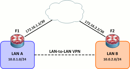
Today we're going to look at LAN-to-LAN VPNs using the pair of ASA 5505s in the community lab. LAN-to-LAN VPNs are typically used to transparently connect geographically disparate LANs over an untrusted medium (e.g. the public Internet). Here we'll see how to configure a simple L2L VPN as pictured in the below topology in a few simple steps.
Initial Configurations
F1:
interface Vlan1
 nameif outside
 security-level 0
 ip address 172.16.1.2 255.255.255.252
!
interface Vlan2
 nameif inside
 security-level 100
 ip address 10.0.1.1 255.255.255.0
!
route outside 0.0.0.0 0.0.0.0 172.16.1.1 1
F2:
interface Vlan1
 nameif outside
 security-level 0
 ip address 172.16.2.2 255.255.255.252
!
interface Vlan2
 nameif inside
 security-level 100
 ip address 10.0.2.1 255.255.255.0
!
route outside 0.0.0.0 0.0.0.0 172.16.2.1 1
Step 1: ISAKMP Policy
First we need to define an ISAKMP policy. ISAKMP is used to establish the initial asymmetrically encrypted channels between the two endpoints so that they can securely negotiate a pair of one-way IPsec security associations (SAs). For more background on IPsec fundamentals, see my IPsec quick and dirty article.
For simplicity, we'll use a static pre-shared key for ISAKMP authentication (which will be defined in step four).
F1(config)# isakmp policy 1
F1(config-isakmp-policy)# authentication pre-share
F1(config-isakmp-policy)# encryption aes-256
F1(config-isakmp-policy)# hash sha
F1(config-isakmp-policy)# group 2
F1(config-isakmp-policy)# lifetime 86400
F1(config-isakmp-policy)# exit
F1(config)# isakmp enable outside
The finished configuration can be copied verbatim from F1 to F2:
crypto isakmp enable outside
crypto isakmp policy 1
 authentication pre-share
 encryption aes-256
 hash sha
 group 2
 lifetime 86400
Step 2: IPsec Transform Set
An IPsec transform set establishes the encryption and authentication (HMAC) methods to be employed by the IPsec SAs. While it is possible to enable several options, both sides of our VPN will be configured to support only 256-bit AES and SHA-1. Our transform set is named L2L.
F1(config)# crypto ipsec transform-set L2L esp-aes-256 esp-sha-hmac
F2(config)# crypto ipsec transform-set L2L esp-aes-256 esp-sha-hmac
Step 3: Create an ACL to Match Traffic
Next we need to create an access list to match plain (unencrypted) traffic which should be encrypted and routed through the IPsec tunnel between the two LANs. This access list will be referenced by the crypto map we'll create in step five. In the real world, crypto map ACLs can be quite complex. For our purposes, however, we only need to match traffic going between the 10.0.1.0/24 and 10.0.2.0/24 networks.
F1(config)# access-list LAN_Traffic extended permit ip 10.0.1.0 255.255.255.0 10.0.2.0 255.255.255.0
We flip the addresses on F2 to match traffic heading the opposite direction:
F2(config)# access-list LAN_Traffic extended permit ip 10.0.2.0 255.255.255.0 10.0.1.0 255.255.255.0
Step 4: Create a Tunnel Group
A tunnel group holds tunnel configuration parameters, namely the connection type and authentication method. Since we're using pre-shred key authentication, we need to name our tunnel group as the IP address of the remote peer. Also, notice that we must define the connection type (ipsec-l2l) before we can configure the pre-shared key.
F1(config)# tunnel-group 172.16.2.2 ?

configure mode commands/options:
  type  Enter the type of this group-policy
F1(config)# tunnel-group 172.16.2.2 type ipsec-l2l
F1(config)# tunnel-group 172.16.2.2 ?

configure mode commands/options:
  general-attributes  Enter the general-attributes sub command mode
  ipsec-attributes    Enter the ipsec-attributes sub command mode
F1(config)# tunnel-group 172.16.2.2 ipsec-attributes
F1(config-tunnel-ipsec)# pre-shared-key ThisIsAWeakKey
The tunnel group configuration on F2 is identical except that its name changes to 172.16.1.2 (F1's outside interface):
tunnel-group 172.16.1.2 type ipsec-l2l
tunnel-group 172.16.1.2 ipsec-attributes
 pre-shared-key ThisIsAWeakKey
Step 5: Create and Apply a Crypto Map
Finally, we need to create a crypto map (named L2L) to tie together the IPsec transform set, access list, and tunnel group configured in the previous steps. First we match LAN-to-LAN traffic using our access list:
F1(config)# crypto map L2L 1 match address LAN_Traffic
Then we set the VPN peer and IPsec transform set to use:
F1(config)# crypto map L2L 1 set peer 172.16.2.2
F1(config)# crypto map L2L 1 set transform-set L2L
The corresponding crypto map on F2 looks like this:
crypto map L2L 1 match address LAN_Traffic
crypto map L2L 1 set peer 172.16.1.2
crypto map L2L 1 set transform-set L2L
All that's left now is to apply the crypto map to the outside interface on each firewall:
F1(config)# crypto map L2L interface outside
F2(config)# crypto map L2L interface outside
Testing
Our LAN-to-LAN VPN won't actually establish until one of the firewalls detects traffic matching our crypto map's access list (10.0.1.0/24 to 10.0.2.0/24 or vice versa). To initiate the VPN, we can ping from one LAN host to another:
F1_Client# ping 10.0.2.9

Type escape sequence to abort.
Sending 5, 100-byte ICMP Echos to 10.0.2.9, timeout is 2 seconds:
.!!!!
Success rate is 80 percent (4/5), round-trip min/avg/max = 1/2/4 ms
Notice that the far-end LAN client appears to be directly connected to the local client:
F1_Client# traceroute 10.0.2.9

Type escape sequence to abort.
Tracing the route to 10.0.2.9

1 10.0.2.9 8 msec *  0 msec
We can see information about the ISAKMP and IPsec SAs between F1 and F2 with the commands show isakmp sa and show ipsec sa:
F1# show isakmp sa

Active SA: 1
    Rekey SA: 0 (A tunnel will report 1 Active and 1 Rekey SA during rekey)
Total IKE SA: 1

1   IKE Peer: 172.16.2.2
    Type    : L2L             Role    : initiator
    Rekey   : no              State   : MM_ACTIVE

F1# show ipsec sa
interface: outside
    Crypto map tag: L2L, seq num: 1, local addr: 172.16.1.2

      access-list LAN_Traffic permit ip 10.0.1.0 255.255.255.0 10.0.2.0 255.255.255.0
      local ident (addr/mask/prot/port): (10.0.1.0/255.255.255.0/0/0)
      remote ident (addr/mask/prot/port): (10.0.2.0/255.255.255.0/0/0)
      current_peer: 172.16.2.2

      #pkts encaps: 4, #pkts encrypt: 4, #pkts digest: 4
      #pkts decaps: 4, #pkts decrypt: 4, #pkts verify: 4
      #pkts compressed: 0, #pkts decompressed: 0
      #pkts not compressed: 4, #pkts comp failed: 0, #pkts decomp failed: 0
      #pre-frag successes: 0, #pre-frag failures: 0, #fragments created: 0
      #PMTUs sent: 0, #PMTUs rcvd: 0, #decapsulated frgs needing reassembly: 0
      #send errors: 0, #recv errors: 0

      local crypto endpt.: 172.16.1.2, remote crypto endpt.: 172.16.2.2

      path mtu 1500, ipsec overhead 74, media mtu 1500
      current outbound spi: 62323606
...
If your ISAKMP SA never progresses past the MM_WAIT_MSG state, you most likely have a connectivity issue between the two VPN endpoints. See more troubleshooting tips here.
The VPN traffic generated by the ping above looks like this. The first ICMP request across the VPN triggers the building of the VPN and is discarded. The remaining four ICMP requests and responses are encrypted in the eight ESP packets at the end of the capture.
Posted in VPN
Comments
July 11, 2011 at 4:05 a.m. UTC
Is there any special considerations for doing this with IPv6?
July 11, 2011 at 6:53 a.m. UTC
Hello,
I have 2 questions for you :
1/ Do you know any possibility to monitor your VPN ? Like SNMP trapping or anything else to check remotly if it's alive ?
2/ Do you know a way to check since when the VPN goes on ?
July 11, 2011 at 8:28 a.m. UTC
just what I needed: thanks!!
July 11, 2011 at 10:10 a.m. UTC
It's probably worth mentioning that these type of connections are typically done through the ASDM as it reduces the risk of entering a typo.
Also, anyone who attempts this in a live environment should check that traffic directed at the peer isn't caught by a route that points the traffic at the internal interface of the ASA. I've seen this a few times and its easily missed.
Nice article, an example with NAT would be interesting as well.
July 11, 2011 at 1:10 p.m. UTC
Note that in order to bring the VPN up, you must ping from a CLIENT from behind the ASA; by default, just pinging from the ASA itself won't do it (unless you specify the source interface, otherwise it routes externally)
July 11, 2011 at 2:56 p.m. UTC
I hate the way the ASDM creates site-to-site VPNs. I think its messy and confusing and much prefer to create them via a template in notepad or similar and use the cli.
Another thing to consider which also catches some people out is to make sure that if there are global NAT rules in place for certain ranges that need access to the internet, make sure you create a NAT exempt rule for the interesting traffic.
July 11, 2011 at 7:52 p.m. UTC
s/pre-shred/pre-shared
July 11, 2011 at 8:39 p.m. UTC
Very nice. Just a few days ago I posted a video tutorial on how do do this using a GRE tunnel between two routers connected to the internet. Glad to see that the basic steps are the same using ASA or a router.
July 11, 2011 at 10:02 p.m. UTC
Also note that the ASA's may be performing NAT between inside and outside. Because NAT will be performed before checking the crypto ACL, the traffic won't actually match the crypto ACL and won't be sent across the VPN. In this situation, you'll generally configure NAT exemption (i.e. don't NAT 'this traffic').
EDIT: From the documentation at the start of the article: http://www.cisco.com/en/US/docs/security/asa/asa82/configuration/guide/nat_bypassing.html#wp1080803
July 12, 2011 at 7:00 a.m. UTC
The command "packet-tracer" is good for testing, too.
July 12, 2011 at 11:34 a.m. UTC
Just a small point!!
Isn't it recommended to Run DH Group 5 when using AES 256 bit encryption as group 2 and lower can sometimes run into problems with the sizes of AES 256...
July 12, 2011 at 6:43 p.m. UTC
@IanJf
I had read as well alright. A quick google search hasn't returned any recommendations though and I'm too lazy right now to check my books. :)
July 12, 2011 at 7:34 p.m. UTC
Might worth nothing that PFS (Perfect Forward Secrecy) option can be enabled in the crypto map along with various idle and session timer lengths parameters which are configurable in both the crypto map section and the isakmp policy section.
Additionally, running debug, it would be very helpful to point out that Phase 1 of the tunnel refers to ISAKMP policy, while Phase 1.5 is the preshared key, and Phase 2 is IPSec configuration which is managed by the crypto map statement. Those are key information when debugging a failed vpn session and trying to figure out which phase you failed on and examine the configuration closer...
Jeremy, its a great post!!! Thanks
July 12, 2011 at 9:07 p.m. UTC
What are the main differences between LAN-to-LAN via:
1. ASA (as described)
2. GRE
3. L2TPv3
TCO of Hardware? Throughput? Security details?
July 13, 2011 at 5:24 p.m. UTC
The use of VLAN1 = bad security practice.
July 14, 2011 at 2:35 p.m. UTC
@Kris it is probably better to take l2tpv3 out of the comparison as it is a different service all together - layer 2 delivery over a l3 cloud.
@nola you are correct when it comes to switches, it is a completely different ideology on ASAs. The vlan should be well protected with access-lists for permissions.
July 19, 2011 at 6:18 a.m. UTC
That configuration is the same as for the 1841 and 2800?
July 31, 2011 at 1:17 a.m. UTC
@nola @jw21 vlan1 on access ports is only a bad idea if vlan1 is the native vlan on your trunks.
October 6, 2011 at 8:59 a.m. UTC
A Question. If there is LAN-to-LAN VPN using the pair of ASA 5505s between 2 sites. Can you have a subnetwork within one of the sites and connect to the subnetwork from a client?
I am typacillty thinking, Headoffice to branch VPN as described in the article. Then there is a project LAN that is (only) connected to the headoffice LAN via an ASA device. So, in the Headoffice you have to VPN from a client PC to the project network and at the branch you do the same, provided that the branch is connected via it's VPN to the head office.
October 6, 2011 at 1:42 p.m. UTC
I have one site with multi site connections through WAN. I have done similar configurations, but got two problem.
1. From one of the branches I can initiate, but from the main site I cann't.
2. The same configuration done on the 2nd site but I cann't initiate from that site. WAN link is ok.
Please sugest
October 6, 2011 at 2:11 p.m. UTC
A Question. I connect LAN-to-LAN VPN using the ASA 5510 at the main site ASA5505 at the other sites through WAN. I have done similar configuration on the main site and two other sites. Ican ping and intiate from the inside of one of the sites, but I canon't ping and intiate from the main site. on the other hand eventhough the same configuration is done, I can ping the outside network of the main site, but I cann't ping and initiate the inside network of the main site.
Please comment
October 27, 2011 at 10:18 a.m. UTC
I'm running into some trouble with the ASA 5520. I have two identical units for the purpose of failover, the problem is that if I were to displace the cable for an uplink to the switch, it will not failover to the second ASA. However, if I were to power down the ASA completely it will switchover to the secondary ASA. Any help on this would greatly appreciated.
January 20, 2012 at 2:30 p.m. UTC
thanks for the post, nice update badly needed this...
January 30, 2012 at 11:27 p.m. UTC
I like the article, but it doesn't really discuss a scenario where NAT translation is needed or wanted. For example:
Local Networks needing VPN access (on "inside" interface):
192.168.10.0/24, 192.168.20.0/24, 192.168.30.0/24
Public IP address (on "outside" interface): 1.1.1.1/24
Public IP address (some vendor firewall): 1.1.1.2/24
Vendor's network on "inside" interface: 10.10.10.0/25
Server A: 10.10.10.10
Server B: 10.10.10.20
In this scenario, I do not want my local workstations to connect to 10.10.10.10. I want them to connect to some translated IP, like 172.16.0.10. Also, I want the vendor to see my source IP as 172.16.x.x.
Example: Workstation A, 192.168.10.100 wants to Connect to Server A. However, they should not connect to 10.10.10.10, but 172.16.0.10 instead. When looking at the logs on Server A, the source IP of the connection should not be 192.168.0.10, but some translated IP.
I know this is easily possible, I'm just muddy on how to do it.
July 12, 2012 at 8:23 p.m. UTC
i configured site to site VPN beetwen the asa 5505 (asa 8.4.2) and the asa 5510 (asa 8.4.4). how i can configure that the users from one side use internet and the site to site vpn in same time? the outside interface of asa5505 have address 10.15.100.8, the gateway for this network(10.15.100.0/24) is 10.15.100.1. this address of asa is nat-ed on public ip address.before LAN (10.15.100.0/24) has had many computers and used internet over the gateway 10.15.100.1 and now all computers must be move on behind asa5505. i configured the site to site vpn but internet doesn't work. pls help me. thanks
ps: this option is split tunneling? how it configure?
September 14, 2012 at 11:09 a.m. UTC
Hi,
I have a problem! I am configuring Site-to-Site VPN with another company. I already make a couple of tunnels but with this one I have a problem. They I already using on their side my local network 192.168.10.0/24 (server is 192.168.10.10) so we need to use imaginary network 172.16.0.5 as server address. Now I need to do NAT 172.16.0.5 to 192.168.10.10 but I am not so good in that.
Can anyone help me? I am using Cisco ASA 5510 (8.4)and ASDM 6.4
January 25, 2013 at 7:07 a.m. UTC
Hey can this be done using dynamic ip addresses between the peers . Would be nice if you could put a dyndns alias as the peer address .
March 25, 2013 at 4:05 a.m. UTC
Good Article! But may anyone tell me functionality wise, what would be the difference between this and a normal site-to-site ipsec vpn?
May 9, 2013 at 4:04 p.m. UTC
Does LAN A and LAN B have to be directly connected to the Inside interfaces on the routers/firewalls (F1/F2) for this configuration to work? I have the following topology that is not, and it's failing.
(LAN A)-(L3 SW)-(Subnet X)-(F1)-(L3 SW)-(F2)-(Subnet Y)-(L3 SW)-(LAN B)
November 4, 2013 at 4:04 p.m. UTC
Will this configuration work is the two ASAs are directly connected with an ethernet cable. I have completed the above configuration and I am still unable to get any traffic to travel between my ASAs.
April 6, 2014 at 12:25 a.m. UTC
Perfect! Thanks for your time to give us that.
December 27, 2014 at 10:24 p.m. UTC
Hi all
I struggle with Cisco but this article has really helped. Here's another tip - use a Cisco VPN configuration generator to start your configuration off, and then tweak it from there. Here's a good one I use - http://www.whyaws.com/tools/cisco_gen.htm
Tom
February 18, 2015 at 10:19 p.m. UTC
Can someone answer this question? Thanks
Will this configuration work is the two ASAs are directly connected with an ethernet cable. I have completed the above configuration and I am still unable to get any traffic to travel between my ASAs.
March 14, 2015 at 12:41 a.m. UTC
New2ASA - if you follow the diagram/config exactly, you'll need some device (router, L3 switch) to represent the cloud - as the outside interfaces on each ASA are on different subnets and cannot route to each other.
April 19, 2015 at 6:33 p.m. UTC
Got this example working great in the lab, but I cannot figure out how to get this working if one side is in transparent mode. L2 Firewalls can terminate VPN management connections. However, I cannot find a good config anywhere.
September 30, 2015 at 10:55 a.m. UTC
hi Guys
im a newbie and have a question about site to site VPN configuration, my scenario is there are 2 branch offices and each office has an ADSL connection(with ADSL router) and a CISCO router, i want to configure the cisco routers to establish a site to site vpn (IPSEC Tunnel) between the offices, each ADSL connection has a static ip configured,so how can i achieve this since the cisco routers dont have the static ips configured and is sitting between the ADSL routers and the LAN?,
December 6, 2015 at 3:50 p.m. UTC
@rockercya
Simple, port forward ports UDP 4500 and UDP 500 from the ADSL routers to the Cisco ASA's outside interface.
Then the peer IP will be your ADSL routers which will port forward UDP4500 and UDP500 do your ASA's.
January 14, 2016 at 9:58 a.m. UTC
Hi,
Can someone please clear something up for me.
On Site-To-Site VPNs do you need to add entries into the access-rules on the ASA firewall to allow the VPN traffic out or does VPN traffic bypass the interface access-lists??
I know that by default an ASA will allow traffic from higher security to lower security interfaces but if I configure a VPN and there is an access-rule blocking all ICMP will I be able to ping across the VPN?
Whenever I read info relating to configuring VPNs there is no step to add a rule but I have a firewall where traffic won't pass outbound without access-rules. (sysopt connection permit is not turned off). So I'm not sure whether this is normal behaviour or whether it's a bug.
March 13, 2016 at 4:41 p.m. UTC
Thanks for sharing this valuable information. That helped me a lot with my labs on GNS3.
March 21, 2016 at 4:49 p.m. UTC
Hey guys, I know this is a relatively old post but I'm having an issue with this set up.
When I ping from test host to other test host, the tunnel is established ( State : MM_ACTIVE ), but traffic doesn't make it across.
I've tested initiating the tunnel by generating traffic from either side to verify the ACLs match the traffic correctly.
Any ideas? Packet capture on the WAN-simulating route shows the encrypted traffic is making it across. No replies though.
Thanks
August 26, 2016 at 9:05 a.m. UTC
Any illustrations as an example on the configuration in required in the cloud of the Topology above? Thanks.