The premiere source of truth powering network automation. Open and extensible, trusted by thousands.
NetBox is now available as a managed cloud solution! Stop worrying about your tooling and get back to building networks.
Keeping Topology Drawings Clean
By stretch | Wednesday, April 13, 2011 at 1:00 a.m. UTC
People often try to cram too much information onto a network topology drawing, which results in cluttered diagrams that are difficult to follow. While it is commendable to want to convey every detail of a network's architecture, these details can be arranged in two categories: things that go on a topology drawing, and things that go on a spreadsheet. The difference between the two can be determined by keeping in mind the purpose of a topology drawing, which is simply to convey how packets flow across a network. Details which aren't needed to support this function belong on a spreadsheet or in some similar database.
Below are my personal recommendations regarding what goes where. Your own approach might differ somewhat but these rules have worked well for me.
Topology Drawing
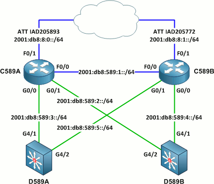
Device ID. This is usually a hostname. Leave off any domain suffixes. Avoid generic labels like "gateway router" or "firewall."
Link prefixes. Routed links are typically labeled with their respective IP subnets. Depending on the scope of the drawing, it may also be desirable to label device interface addresses.
VLANs. Layer two trunks might be labeled with the VLANs they carry, if appropriate.
Interface IDs. Label physical and logical interfaces with their abbreviated forms, e.g. F0/0 instead of FastEthernet0/0 (or Fa0/0 if it is necessary to distinguish between FastEthernet and FDDI interfaces).
Circuit IDs. When depicting a link through a service provider, always include its circuit ID.
Link bandwidth. Bandwidths are typically conveyed by color-coding links with contrasting colors (for example, don't use orange and yellow where they might be confused). Avoid explicitly labeling the bandwidth of links except where particularly of interest (for example, WAN circuits).
Device Spreadsheet
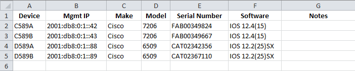
Device ID. This should exactly match what's on the drawing. May include domain suffix (preferably in a separate column for easier readability).
Management IP address. This should be a loopback or other virtual interface that will remain reachable so long as there is at least one functional path to the device. (If you haven't designated management addresses for all of your devices, fix that first, then come back to the drawing.)
Serial number. Necessary for accounting and inventory purposes.
Make and model. Manufacturer and model number, e.g. Cisco 1841.
Software version. E.g. Cisco IOS 12.4(25)T.
Miscellaneous. Installed modules, deployment date, notes, etc.
You might also opt to include a spreadsheet containing per-link details. This should be a sheet or table separate from your device spreadsheet. It should include all the relevant details from the topology drawing (IP prefixes, device and interface IDs, bandwidth) plus whatever additional information you care to add.
Posted in Network Diagrams
Comments
April 13, 2011 at 1:27 a.m. UTC
You can always use Visio to make your spreadsheet using customer property sets on the device that way when you add a device to your diagram, you can just pull the spreadsheet out of the custom properties.
April 13, 2011 at 2:50 a.m. UTC
Good tips. I also like to put many of the label features in their own layers in Visio, such as IP subnet labels, equipment labels, and port labels, and legend/note blocks. This allows the customer to print various versions of the diagram based on security concerns or limiting the diagram's content to relevant information for its recipient.
April 13, 2011 at 8:10 p.m. UTC
I dig the hostnames. Guess the ol Comm Squardon has a lil place in your heart... 589 was the bldg number for the NCC, wasn't it? Keep up the good work man. Later...Ed
April 14, 2011 at 1:27 p.m. UTC
The most important point is never, ever, ever, try and mix layer 1/2 and layer 3 topology on the same diagram. Separate diagrams for each of the two. And yes kiddies, that means switches should not occur on L3 diagrams (if it does L3, it's a router)...
April 14, 2011 at 6:26 p.m. UTC
I keep my diagrams pretty much the same layout. I also add the Loopback or Management Interface Address under the hostname. That way the diagram can act as a quick access map.
April 14, 2011 at 9:31 p.m. UTC
I like to see the model with the hostname along with the loopback. This is also looks like a mixed physical/logical so you may as well include a chart showing - cat6, fiber-mm, fiber-sm, coax, twinax, etc for your cable colors. Dont forget the transparent circle for LAGs and FHRP information as well.
April 16, 2011 at 10:20 p.m. UTC
+1 for not mixing L2 and L3 diagrams... Although very common, it usually gets very confusing and cluttered.
April 23, 2011 at 7:23 p.m. UTC
+2
July 4, 2014 at 12:11 p.m. UTC
I strongly agree you need separate L3-diagrams. Good blog post about those: http://packetpushers.net/how-to-draw-clear-l3-logical-network-diagrams/
October 25, 2014 at 10:43 a.m. UTC
Jeremy,
nice post and yeah clean visio diagram is very handy for understanding network.i saw few of your post and would say your diagram always look very clean.
i would have 1 request hope you full fill we wana learn visio skills from you if you post few blog post how to deal with visio and how to do.i always messed with connectors and shapes and how clean u put labels thats also very messy in my topology so pls guide us on this........looking for a visio tutorial from your side.i wish you will do