The premiere source of truth powering network automation. Open and extensible, trusted by thousands.
NetBox is now available as a managed cloud solution! Stop worrying about your tooling and get back to building networks.
Multiple DMVPNs on a Single Hub
By stretch | Monday, January 9, 2012 at 1:31 a.m. UTC
I've touched on the fundamentals of DMVPN before, but today I'm going to expand upon my previous discussion and experiment with configuring multiple DMVPN clouds on a single pair of redundant headend routers. The scenario we'll use is that of a service provider offering DMVPN connectivity to two unrelated customers: Both customers need connectivity among their own sites and to the ISP, but must not be able to communicate with one another. Accordingly, each customer must use its own unique pre-shared key for authentication.
Our overall topology looks like this:
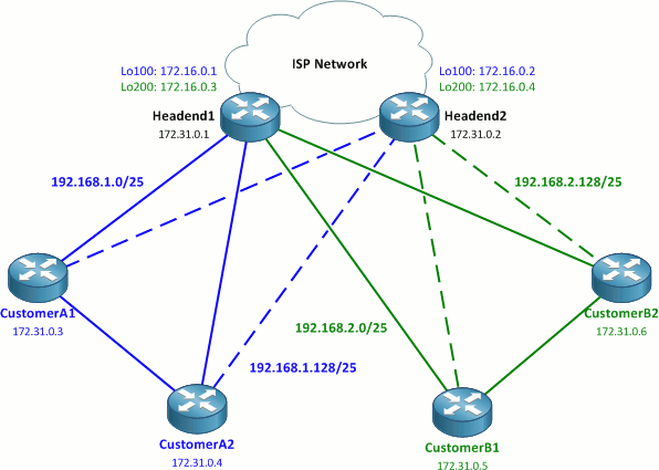
The 172.16.0.0/20 space represents public address space; in a real-world deployment, these would typically be effectively random public IP addresses.
The two ISP headend routers connect the four sites, two per customer, to the ISP network. Each headend router has two loopback interfaces (addressed out of 172.16.0.0/24) to which the DMVPN tunnels will be terminated. Per Cisco's DMVPN design guide, each customer will have two redundant DMVPN tunnels, one to each headend router. This adds up to a total of four DMVPN networks. Beware: this lab might get a little muddy, but I'll do my best to keep things clear.
Crypto Configuration
We'll start off by laying our crypto foundations. We'll use a single ISAKMP policy and IPsec transform-set common to all routers in the lab:
All routers
crypto isakmp policy 10
 encr aes 256
 authentication pre-share
 group 2
!
crypto ipsec transform-set ESP_AES256_SHA_TRANSPORT esp-aes 256 esp-sha-hmac
 mode transport
Next, we'll configure the necessary crypto profiles on the headend routers. Note that the keyrings and ISAKMP profiles are explicitly sourced from the loopback interfaces: This ensures that the correct pre-shared key is applied to each DMVPN spoke router based on the destination IP address of incoming encrypted packets.
Headend routers
crypto keyring CustomerA
  local-address Loopback100
  pre-shared-key address 0.0.0.0 0.0.0.0 key MySecretKeyA
crypto keyring CustomerB
  local-address Loopback200
  pre-shared-key address 0.0.0.0 0.0.0.0 key MySecretKeyB
!
crypto isakmp profile CustomerA
   keyring CustomerA
   match identity address 0.0.0.0
   local-address Loopback100
crypto isakmp profile CustomerB
   keyring CustomerB
   match identity address 0.0.0.0
   local-address Loopback200
!
crypto ipsec profile CustomerA
 set transform-set ESP_AES256_SHA_TRANSPORT
 set isakmp-profile CustomerA
!
crypto ipsec profile CustomerB
 set transform-set ESP_AES256_SHA_TRANSPORT
 set isakmp-profile CustomerB
The configuration of the spoke routers is very similar to that of the headend routers, but shorter since we're only including configuration applicable to the respective customers. Here we can use a single wildcard mask to match the pre-shared key.
Customer A routers
crypto keyring DMVPN
  pre-shared-key address 0.0.0.0 0.0.0.0 key MySecretKeyA
!
crypto isakmp profile DMVPN
   keyring DMVPN
   match identity address 0.0.0.0
!
crypto ipsec profile DMVPN
 set transform-set ESP_AES256_SHA_TRANSPORT
 set isakmp-profile DMVPN
Customer B routers
crypto keyring DMVPN
  pre-shared-key address 0.0.0.0 0.0.0.0 key MySecretKeyB
!
crypto isakmp profile DMVPN
   keyring DMVPN
   match identity address 0.0.0.0
!
crypto ipsec profile DMVPN
 set transform-set ESP_AES256_SHA_TRANSPORT
 set isakmp-profile DMVPN
DMVPN Configuration
With crypto out of the way, we can move on to DMVPN tunnel configuration. First we create two unique tunnels on both of the two headend routers, one in either customer VRF.
Headend1
ip vrf CustomerA
 rd 65000:100
!
ip vrf CustomerB
 rd 65000:200
!
interface Tunnel100
 ip vrf forwarding CustomerA
 ip address 192.168.1.1 255.255.255.128
 no ip redirects
 ip nhrp map multicast dynamic
 ip nhrp network-id 101
 tunnel source Loopback100
 tunnel mode gre multipoint
 tunnel key 101
 tunnel protection ipsec profile CustomerA
!
interface Tunnel200
 ip vrf forwarding CustomerB
 ip address 192.168.2.1 255.255.255.128
 no ip redirects
 ip nhrp map multicast dynamic
 ip nhrp network-id 201
 tunnel source Loopback200
 tunnel mode gre multipoint
 tunnel key 201
 tunnel protection ipsec profile CustomerB
Headend2
ip vrf CustomerA
 rd 65000:100
!
ip vrf CustomerB
 rd 65000:200
!
interface Tunnel100
 ip vrf forwarding CustomerA
 ip address 192.168.1.129 255.255.255.128
 no ip redirects
 ip nhrp map multicast dynamic
 ip nhrp network-id 102
 tunnel source Loopback100
 tunnel mode gre multipoint
 tunnel key 102
 tunnel protection ipsec profile CustomerA
!
interface Tunnel200
 ip vrf forwarding CustomerB
 ip address 192.168.2.129 255.255.255.128
 no ip redirects
 ip nhrp map multicast dynamic
 ip nhrp network-id 202
 tunnel source Loopback200
 tunnel mode gre multipoint
 tunnel key 202
 tunnel protection ipsec profile CustomerB
A few details of these tunnel configurations worth pointing out:
- Tunnel100 is created on both headend routers for Customer A; Tunnel200 for Customer B. A separate /25 network is assigned to each of the four tunnels.
- The tunnel interfaces are sourced from the loopback interfaces.
- Each tunnel has been assigned a unique NHRP network ID and tunnel key. These don't necessarily need to match, but it keep things a bit tidier when they do.
- The
sharedparameter has been appended to thetunnel protection ipsec profile DMVPNstatement. This is necessary because both tunnels reference the same IPsec profile. Also note that the tunnels must be sourced from a physical interface identifier for this to take effect.
The spoke router tunnel interfaces are configured very similarly to the headend routers, with the addition of NHS specifications. Unlike the headend router tunnels, these are sourced from physical interfaces.
CustomerA1
interface Tunnel1
 ip address 192.168.1.2 255.255.255.128
 no ip redirects
 ip nhrp map 192.168.1.1 172.16.0.1
 ip nhrp network-id 101
 ip nhrp nhs 192.168.1.1
 tunnel source FastEthernet0/0
 tunnel mode gre multipoint
 tunnel key 101
 tunnel protection ipsec profile DMVPN shared
!
interface Tunnel2
 ip address 192.168.1.130 255.255.255.128
 no ip redirects
 ip nhrp map 192.168.1.129 172.16.0.2
 ip nhrp network-id 102
 ip nhrp nhs 192.168.1.129
 tunnel source FastEthernet0/0
 tunnel mode gre multipoint
 tunnel key 102
 tunnel protection ipsec profile DMVPN shared
CustomerA2
interface Tunnel1
 ip address 192.168.1.3 255.255.255.128
 no ip redirects
 ip nhrp map 192.168.1.1 172.16.0.1
 ip nhrp network-id 101
 ip nhrp nhs 192.168.1.1
 tunnel source FastEthernet0/0
 tunnel mode gre multipoint
 tunnel key 101
 tunnel protection ipsec profile DMVPN shared
!
interface Tunnel2
 ip address 192.168.1.131 255.255.255.128
 no ip redirects
 ip nhrp map 192.168.1.129 172.16.0.2
 ip nhrp network-id 102
 ip nhrp nhs 192.168.1.129
 tunnel source FastEthernet0/0
 tunnel mode gre multipoint
 tunnel key 102
 tunnel protection ipsec profile DMVPN shared
CustomerB1
interface Tunnel1
 ip address 192.168.2.2 255.255.255.128
 no ip redirects
 ip nhrp map 192.168.2.1 172.16.0.3
 ip nhrp network-id 201
 ip nhrp nhs 192.168.2.1
 tunnel source FastEthernet0/0
 tunnel mode gre multipoint
 tunnel key 201
 tunnel protection ipsec profile DMVPN shared
!
interface Tunnel2
 ip address 192.168.2.130 255.255.255.128
 no ip redirects
 ip nhrp map 192.168.2.129 172.16.0.4
 ip nhrp network-id 202
 ip nhrp nhs 192.168.2.129
 tunnel source FastEthernet0/0
 tunnel mode gre multipoint
 tunnel key 202
 tunnel protection ipsec profile DMVPN shared
CustomerB2
interface Tunnel1
 ip address 192.168.2.3 255.255.255.128
 no ip redirects
 ip nhrp map 192.168.2.1 172.16.0.3
 ip nhrp network-id 201
 ip nhrp nhs 192.168.2.1
 tunnel source FastEthernet0/0
 tunnel mode gre multipoint
 tunnel key 201
 tunnel protection ipsec profile DMVPN shared
!
interface Tunnel2
 ip address 192.168.2.131 255.255.255.128
 no ip redirects
 ip nhrp map 192.168.2.129 172.16.0.4
 ip nhrp network-id 202
 ip nhrp nhs 192.168.2.129
 tunnel source FastEthernet0/0
 tunnel mode gre multipoint
 tunnel key 202
 tunnel protection ipsec profile DMVPN shared
Whew! We're finally done with configuration. We can verify that the DMVPN spoke routers have dutifully established tunnels to both of the headend routers with the command show dmvpn. The IP address listed for each spoke router in the "Peer NBMA Addr" column is its external (public) IP address.
Headend1# show dmvpn
Legend: Attrb --> S - Static, D - Dynamic, I - Incomplete
    N - NATed, L - Local, X - No Socket
    # Ent --> Number of NHRP entries with same NBMA peer
    NHS Status: E --> Expecting Replies, R --> Responding
    UpDn Time --> Up or Down Time for a Tunnel
==========================================================================

Interface: Tunnel100, IPv4 NHRP Details
Type:Hub, NHRP Peers:2,

# Ent  Peer NBMA Addr Peer Tunnel Add State  UpDn Tm Attrb
 ----- --------------- --------------- ----- -------- -----
     1      172.31.0.3     192.168.1.2    UP 00:05:50     D
     1      172.31.0.4     192.168.1.3    UP 00:05:40     D

Interface: Tunnel200, IPv4 NHRP Details
Type:Hub, NHRP Peers:2,

# Ent  Peer NBMA Addr Peer Tunnel Add State  UpDn Tm Attrb
 ----- --------------- --------------- ----- -------- -----
     1      172.31.0.5     192.168.2.2    UP 00:05:41     D
     1      172.31.0.6     192.168.2.3    UP 00:05:45     D
We can test spoke-to-spoke connectivity by pinging from one customer router to the other. The spoke routers should be able to reach one another via either DMVPN tunnel.
CustomerA1# ping 192.168.1.3

Type escape sequence to abort.
Sending 5, 100-byte ICMP Echos to 192.168.1.3, timeout is 2 seconds:
!!!!!
Success rate is 100 percent (5/5), round-trip min/avg/max = 4/7/12 ms
CustomerA1#show dmvpn
Legend: Attrb --> S - Static, D - Dynamic, I - Incomplete
    N - NATed, L - Local, X - No Socket
    # Ent --> Number of NHRP entries with same NBMA peer
    NHS Status: E --> Expecting Replies, R --> Responding
    UpDn Time --> Up or Down Time for a Tunnel
==========================================================================

Interface: Tunnel1, IPv4 NHRP Details
Type:Spoke, NHRP Peers:2,

# Ent  Peer NBMA Addr Peer Tunnel Add State  UpDn Tm Attrb
 ----- --------------- --------------- ----- -------- -----
     1      172.16.0.1     192.168.1.1    UP 00:06:32     S
     1      172.31.0.4     192.168.1.3    UP 00:00:04     D

Interface: Tunnel2, IPv4 NHRP Details
Type:Spoke, NHRP Peers:1,

# Ent  Peer NBMA Addr Peer Tunnel Add State  UpDn Tm Attrb
 ----- --------------- --------------- ----- -------- -----
     1      172.16.0.2   192.168.1.129    UP 00:06:26     S

CustomerA1# ping 192.168.1.131

Type escape sequence to abort.
Sending 5, 100-byte ICMP Echos to 192.168.1.131, timeout is 2 seconds:
!!!!!
Success rate is 100 percent (5/5), round-trip min/avg/max = 4/6/8 ms
CustomerA1#show dmvpn
Legend: Attrb --> S - Static, D - Dynamic, I - Incomplete
    N - NATed, L - Local, X - No Socket
    # Ent --> Number of NHRP entries with same NBMA peer
    NHS Status: E --> Expecting Replies, R --> Responding
    UpDn Time --> Up or Down Time for a Tunnel
==========================================================================

Interface: Tunnel1, IPv4 NHRP Details
Type:Spoke, NHRP Peers:2,

# Ent  Peer NBMA Addr Peer Tunnel Add State  UpDn Tm Attrb
 ----- --------------- --------------- ----- -------- -----
     1      172.16.0.1     192.168.1.1    UP 00:06:44     S
     1      172.31.0.4     192.168.1.3    UP 00:00:16     D

Interface: Tunnel2, IPv4 NHRP Details
Type:Spoke, NHRP Peers:2,

# Ent  Peer NBMA Addr Peer Tunnel Add State  UpDn Tm Attrb
 ----- --------------- --------------- ----- -------- -----
     1      172.16.0.2   192.168.1.129    UP 00:06:38     S
     1      172.31.0.4   192.168.1.131    UP 00:00:02     D
Observe how the spoke routers dynamically learn about their peers via NHRP requests sent to the NHS. Once the peer NBMA address has been learned, a new IPsec tunnel is built and the two peers communicate with one another directly.
From this point, one would move on to configuring a routing protocol to run across the DMVPN networks, but that's a topic in its own right and best left for another day.
Posted in VPN
Comments
January 9, 2012 at 1:46 a.m. UTC
Nice article Jeremy! I'm glad to see you have taken some time away from your busy schedule to post a new blog entry!
Just a heads up to users with 6500/7500s wanting to use DMVPNs - Sup720s are required to be DMVPN hub or spoke. Also, the 'tunnel key' forces the traffic to be software switched. Source: http://www.cisco.com/en/US/docs/ios/12_2t/12_2t13/feature/guide/ftgreips.html
I know it's quasi-off topic, but unfortunately I know this from experience. :)
January 9, 2012 at 2:17 a.m. UTC
Ya! Your back! I've checked in everyday, hoping.
January 9, 2012 at 8:55 a.m. UTC
Does this design therefore require a specific loopback on the head end per customer? That would burn a lot of IPv4 public address space...
Would it be possible to achieve this with only one public IP?
January 9, 2012 at 10:20 a.m. UTC
Hi Jeremy, Nice Article, Glad to see an update from you, I look forward to labbing this out, some of your previous articles (particularly on VRF and MPLS) have really helped me out, and your cheat sheets are awesome
January 9, 2012 at 1:09 p.m. UTC
Steve Wright: Great question! I've come with only two ways to configured multiple DMVPNs with unique keys on a single hub:
- Use one loopback per DMVPN and bind a wildcard pre-shared key to that IP (as in this lab), or;
- Explicitly define each pre-shared key per DMVPN spoke individually, which requires one to know the external IP address of every spoke ahead of time.
I'd love to hear if anyone has found a more scalable option.
January 9, 2012 at 3:02 p.m. UTC
I've used a third way, but it takes some backend infrastructure to power it... IPsec certificate-based authentication instead of pre-shared keys.
There's a lot more scalability and matching/filtering you can do with certificate authentication, such as matching on CN/DN, issuer name, and other items. The down side is that it's certainly more complicated than IPsec PSKs, but it gets around the "pre-shared key address 0.0.0.0 0.0.0.0" issue of matching the wrong tunnel to the wrong PSK.
For a very static DMVPN, you can define each PSK individually, but otherwise this becomes a huge pain for a very dynamic/large DMVPN.
January 10, 2012 at 6:01 p.m. UTC
It may be off topic but one thing to note with DMVPN if using EIGRP is disabling split horizon and eigrp next-hop-self on the headend routers if they're in a hub and spoke connection. The first one for obvious reasons. The second one is to allow correct next hop resolution for spoke to spoke tunnels. Figured I'd save someone the pain of figuring it out if they look here later.
April 16, 2012 at 4:38 p.m. UTC
Hey Jeremy, Nice Work. I am trying to do something a bit similar and I am wondering if you may be able to point me in the right direction.
I have two Main Sites and about 5 or 6 branch sites.
I use a public WWAN that interconnects everyone. a DMVPN cloud is built on that WAN to secure the commenucations as it passes over the WAN.
I need to setup the second Main Site as a failover site and I also need to add Metro Ethernet to mix tp become the primary network.
Therefore, I have two main sites which are each connected to the WWAN and to the Metro E service.
I have 6 Branch Offices which are each connected to the Metro and to the WWAN.
I want to use the Metro as the Primary and the WWAN as the secondary. I am thinking to setup a separate DMVPN cloud on the Metro and connect each branch router to both clouds. Both clouds will have separate sub-nets. Each Site will also contain a Hub that is also connected to both the WWAN and the Metro Ethernet.
What is need to achieve is Redundancy. if the Metro Ethernet goes down, the branch offices should switch to the WWAN and vice versa.
Any ideas you can share?
Thanks in advance.
July 10, 2012 at 1:26 a.m. UTC
Jeremy,
Hello, can you post the IP routing design you used for the DMVPN lab? I have tried to duplicate your DMVPN setup but I am not getting any luck.
The question I have is what are the 172.31.0.X IPs used for? are they used for a P2P link between the customer sites.
Also are you planning on posting the same DMVPN setup but with a routing protocol setup?
Thanks!!
July 19, 2013 at 6:35 a.m. UTC
Thank you. Very helpful post
March 12, 2015 at 1:15 p.m. UTC
This is a really well written article. Nice work.
March 19, 2015 at 2:09 p.m. UTC
Hi,
How would I modify this to use Dynamic DNS addresses instead of IP's?
Cheers Tank