The premiere source of truth powering network automation. Open and extensible, trusted by thousands.
NetBox is now available as a managed cloud solution! Stop worrying about your tooling and get back to building networks.
TCP Slow Start
By stretch | Tuesday, July 5, 2011 at 12:00 a.m. UTC
TCP employs four critical congestion control mechanisms in order to function efficiently under constantly changing network conditions such as those found on the global Internet. These mechanisms are defined in RFC 5681 (and previously in RFCs 2001 and 2581) as slow start, congestion avoidance, fast retransmit, and fast recovery. Today we'll look at how the slow start mechanism is used to increase the initial throughput rate of a TCP connection immediately upon establishment.
Transmission Windows
Before digging into slow start, it is necessary to understand how TCP places limits, called windows, on the amount of data which can be in transit between two endpoints at a given time. Because of the reliable nature of TCP, a TCP sender can transmit only a limited amount of data before it must receive an acknowledgement from the receiver; this is to ensure that any lost segments can be retransmitted efficiently.
There are two variables which affect how much unacknowledged data a sender can send: the receiver window (RWND) advertised by the TCP peer and the sender's own congestion window (CWND). As we've covered in a prior article, the receiver window is the value of the window field in a TCP packet sent by the receiver.
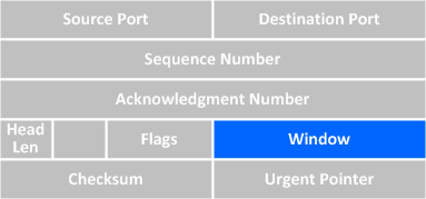
The sender's congestion window, however, is known only to the sender and does not appear on the wire. The lower of the two window values becomes the maximum amount of unacknowledged data the sender can transmit.
So how is the CWND determined? RFC 5681 mandates that the initial CWND value for a connection must be set relative to the sender's maximum segment size (SMSS) for the connection:
If SMSS > 2190 bytes:
IW = 2 * SMSS bytes and MUST NOT be more than 2 segments
If (SMSS > 1095 bytes) and (SMSS <= 2190 bytes):
IW = 3 * SMSS bytes and MUST NOT be more than 3 segments
If SMSS <= 1095 bytes:
IW = 4 * SMSS bytes and MUST NOT be more than 4 segments
The MSS for either side of a TCP connection is advertised as a TCP option in the SYN packets, and both sides use the lower of the two advertised values. An MSS of 1460 bytes is common on the Internet, being derived from a layer two MTU of 1500 bytes (1500 - 20 bytes for IP - 20 bytes for TCP = 1460). According to RFC 5681, an SMSS of 1460 bytes would give us an initial CWND of 4380 bytes (3 * 1460 = 4380). However, in practice the initial CWND size will vary among TCP/IP stack implementations.
Again, remember that the sender's effective transmission window is always the lower of CWND and RWND. As we'll see, the slow start (and later, congestion avoidance) mechanisms are used to dynamically increase (and lower) the sender's transmission window throughout the duration of a TCP connection.
Slow Start
The slow start algorithm can simplified as this: for every acknowledgment received, increase the CWND by one MSS. For example, if our MSS is 1460 bytes and our initial CWND is twice that (2920 bytes), we can initially send up to two full segments immediately after the connection is established, but then we have to wait for our segments to be acknowledged by the recipient. For each of the two acknowledgments we then receive, we can increase our CWND by one MSS (1460 bytes). So, after we receive two acknowledgments back, our CWND becomes 5840 bytes (2930 + 1460 + 1460). Now we can send up to four full segments before we have to wait for another acknowledgment.
An illustration may help solidify this concept. This packet capture shows a 1 MB file being downloaded via HTTP from 174.143.213.184 from the client's perspective. The round-trip time (RTT) between the client and server is about 50 msec. We can produce a graph displaying the progression of the server's CWND over time by opening the capture in Wireshark. Select packet #6 (which contains the first data sent from the server) in the packet list pane and navigate to Statistics > TCP Stream Graph > Time-Sequence Graph (Stevens). You should get a graph that looks like this:
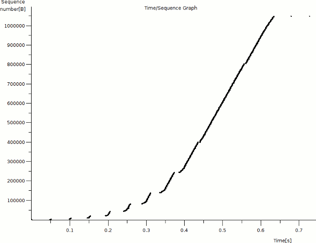
(If your graph doesn't look like this, go back and make sure you have packet #6 selected.)
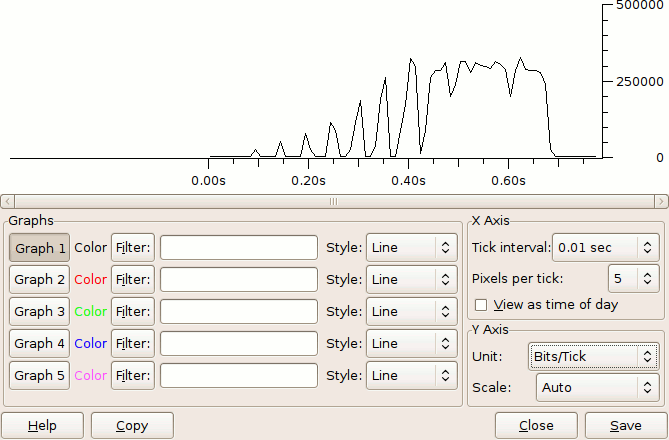
This graph shows the progression of data transfer over time, not speed (the corresponding I/O graph for this capture looks like this, if you're interested). Time (in seconds) is on the x axis and the relative sequence number of each packet is on the y axis. Only packets from the server are shown on this graph. Each dot represents a single packet; clicking on a dot will select the corresponding packet in the list pane (although it's not always easy to click on the exact packet you want). Zoom in on the bottom left corner of the graph by middle-clicking a few times on the origin so that the individual packets become more distinct.
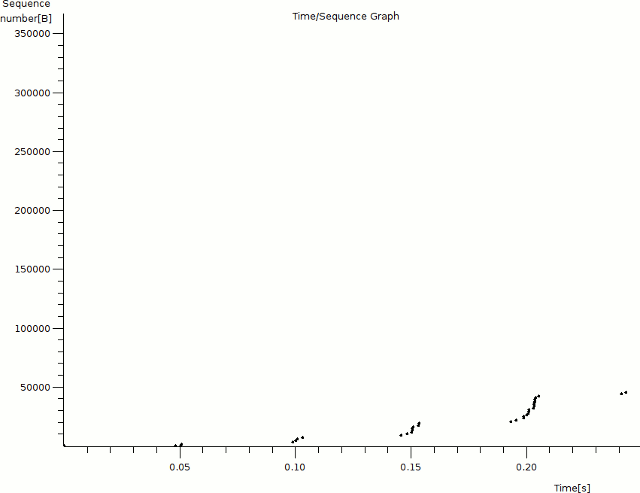
Notice that we see a cluster of packets sent roughly every 50 msec for the first few iterations; this is due to the approximate 50 msec round-trip time between the client and server. At the 0.05s mark, we see the server acknowledging the client's HTTP request (packet #5), followed closely by the first two segments of the response data (packets #6 and #8). At this point the server's CWND is exhausted; it must wait to receive an acknowledgment from the client before it can send any more data.
After another 50 msec or so, the server receives an acknowledgment from the client for each of the two segments it sent, and increases its CWND to from 2920 bytes (2x MSS) to 5840 bytes (4x MSS). The server sends another four segments at 0.10s and then has to wait for another acknowledgment. At around 0.15s, the server receives four more acknowledgments (one for each segment it sent) and further increases its CWND from 4x MSS to 8x MSS (11680 bytes). Next the server sends eight segments and waits again for more acknowledgments. This pattern repeats again at 0.20s with 16 packets. Notice that the server's CWND has been effectively doubling about every 50 msec.
At around the 0.25s mark, however, we stop doubling our CWND: the next cluster is of only 26 segments, not 32 as we might expect. Why? Take a look at the packet list in Wireshark's top pane and scroll down to packet #52. Notice that at this point the client starts sending an ACK only for every two (or occasionally three) segments, not for every individual segment. This effectively halves the rate at which we can continue to increase our CWND: remember that we can only add 1460 bytes (one MSS) per acknowledgment received. The following cluster is of 39 segments, which is 1.5 times (instead of twice) our previous cluster of 26.
Since the rate at which the CWND increases depends on the rate at which the receiver decides to acknowledge segments, slow start doesn't result in a strictly exponential curve. However, we can see from the graph that it does result in a steep gain in throughput over a relatively short period of time. So why is it called "slow start," then? Early implementations of TCP permitted a sender to transmit up to the receiver's full advertised receive window right out of the gate. As you can imagine, this led to substantial loss on slow networks right away, and connections had a hard time getting their throughput rates off the ground. Hence the more relaxed approach of slow start.
Of course, at some point we're going to bump up against the practical throughput limit of the underlying network. When this happens, we begin to lose segments. When loss is detected, or when we reach a specific CWND threshold, TCP transitions from the slow start algorithm to the congestion avoidance algorithm, which we'll cover in a future article.
Posted in Packet Analysis
Comments
July 5, 2011 at 4:08 a.m. UTC
Great article! Just one question.
"Notice that at this point the client starts sending an ACK only for every two (or occasionally three) segments, not for every individual segment."
Why is this happening? Is this a vendor specific implementation or a some kind of Block Acknowledgement feature of TCP?
Cheers, TacACK
July 5, 2011 at 4:42 a.m. UTC
Hi Jeremy,
Great article, thanks! However I am a bit of confused after digging to the captured file.
From the file:
1st cluster (2 segments):
Server send #6,8 and client ack #7,9. So next round is 2+2=4 segments.
2nd cluster (4 segments):
Server send #10,12,14,16 and client ack #11,13,15,17. So next is 4+4=8 segments.
3rd cluster (8 segments):
Server send #18,20,22,24,26,28,30,32 and client ack #19,21,23,25,27,29,31,33. So next is 8+8=16 segments.
Am I correct?
But in the 4th cluster (16 segments), I found:
Server send #34,36,38,40,42,44,46,48,50,51,53,54,56,57,58,60(?) and
client ack #35,37,39,41,43,45,47,49,52,55,59. That's 11 Acks.
Another question:
#59 is the ack for #56,57,58, if #60 is the 16th segment server sent, why the server continues sending the next cluster (#61) before receiving the ack of #60?
Could you please shed me light on this?
Thanks a lot!
July 5, 2011 at 6:27 a.m. UTC
I have just been reading up on RFC 1323 and 2018 - very similar stuff. Might be worth reading this RFC for further info. Thanks Stretch.
July 5, 2011 at 8:16 a.m. UTC
tacack,
Reading through RFCs 5681(4.2), and more specifically 1122(4.2.3.2), it appears that an ACK maybe be sent for every few segments to increase network efficiency. Given that the RFC states that 'delayed ACK' as it is known, SHOULD be implemented, some vendors may implement it, and others may not
July 5, 2011 at 9:53 a.m. UTC
Thanks Stuart!
July 5, 2011 at 1:35 p.m. UTC
Wow I like your article very much. I wish you were my teacher.
July 5, 2011 at 6:00 p.m. UTC
hey, jeremy. how did your job go? was is good and pleased you? i.e. was it what you expected or after you saw your position it just disappointed you !!!!
July 6, 2011 at 1:31 a.m. UTC
I'm sure many of you have already seen it, but for those who haven't, here's a paper from some Google folks regarding a proposed increase to the initial CWND far above the values referenced in RFC 5681: http://code.google.com/speed/articles/tcp_initcwnd_paper.pdf
July 6, 2011 at 2:58 a.m. UTC
Articles like these ones are the ones I really enjoy.
July 7, 2011 at 4:57 p.m. UTC
Stretch,
Thanks a lot.
July 13, 2011 at 8:04 p.m. UTC
Great article.. For anohter great explenation look up the Cisoc Internet Protocol Journals (IPJ) articles titled "TCP Performance". There were publised in 2000 and were 2 segemnts. Execllent breakdown on how TCP works and it congestion handling mechanisims.. The Cisco site has an archive of all past IPJs and they are a great resource.
Regards...
August 22, 2011 at 6:16 a.m. UTC
Hi, Jeremy,
Thanks for the great detailed posting, I've learnt a lot from that and when I dig into the more detail, I found something that I would like to share:
seems the RTT is not 50ms, but rather short, as can be seem from TCP RTT graph, which is ~0.00002s
Seems the 50ms wait is the mechanism in server scheduling.
and also the traffic is from server to client, the congestion control side should be server.
October 30, 2011 at 8:07 a.m. UTC
Nice article, this is really helping me with realizing slow start within a time/seq graph.
May 1, 2012 at 6:26 a.m. UTC
Hi albert,
The 50 ms RTT also puzzled me. Looking at the trace, the receiver sent ACK right after with 0.0002s delay (rather than 50ms) on packets #7 and #9.
Can someone elaborate on the server scheduling mechanism? Is it the amount of time the operating system took on the context switch between threads/process?
December 13, 2012 at 5:59 p.m. UTC
Kevin,
the capture is from the user's standpoint, so all ACKs will be immediate. What you need to see is the first 2 packets #6 and #8 were sent from the server at the same time, then there is a ~50ms wait (the time the server waits to hear back from the user's 1st ACK plus the time for the user to receive the next set of data) before the server sends the next 4 packets, #10,#12,#14,#16. Then another RTT of ~50 ms before the next 8 packets (#18,#20,#22,#24,#26,#28,#30,#32) arrive at the user. The # of packets the server can send increases with every ACK, so as ACKs trickle in to the server and new packets are sent, the RTT loses its significance.
February 18, 2013 at 6:52 p.m. UTC
@tacack
You are correct about the 'delayed ACK'. It is a mechanism that can be implemented to improve network efficiency by only acknowledging every second packet. An ACK may be delayed up to 500ms, however an ACK must be sent for every 2nd segment received. Now this creates a funky problem known as "Silly Window Syndrome" when the NAGLE algorithm is turned on one side and delayed ACK is turned on the other side.
NAGLE algorithm does increase network efficiency by waiting to send till it has enough data to fill the packet (MSS) but this comes with the cost of latency.
Great article stretch!!
April 9, 2013 at 8:53 p.m. UTC
Hi Jeremy,
Thanks for the good write up.
I am working on a side project that involves finding server characteristics such as icw, ssthresh etc. I have written the code in python. So far, I have got a rough estimate of icw of a web server, but having a bit of difficulty for finding the ssthresh.
Would you have any idea on going about that?
March 29, 2014 at 1:14 a.m. UTC
I bet many of us are expecting the congestion avoidance algorithm article. Jeremy knowledge in this matter is outstanding.
May 19, 2014 at 8:30 a.m. UTC
Thanks for the crystal clear explanation of slow start. I was looking for some material to prepare my classes. I think that the plots help a lot in understanding what is going on.
I am trying to prepare some lecture notes for the students: https://github.com/jbarcelo/QOS-lecture-notes
BTW, I love the "challenge" questions for posting comments.
January 30, 2015 at 4:16 a.m. UTC
Stretch - great article as always. I think I spot an error though. Above you say "The MSS for either side of a TCP connection is advertised as a TCP option in the SYN packets, and both sides use the lower of the two advertised values." I believe that is wrong. The advertised MSS do not have to be identical - there is no "negotiation", and whatever values are used are used as is. So, one peer could have MSS = 1100 and the other MSS = 1200 and they would just use those verbatim.
July 18, 2015 at 1:43 a.m. UTC
"The MSS for either side of a TCP connection is advertised as a TCP option in the SYN packets, and both sides use the lower of the two advertised values."
Is this correct ? Cant either side talk using different MSS values ?
October 27, 2015 at 2:27 a.m. UTC
@Ebin,
No, that defeats the purpose of connection establishment and windowing which are the reasons TCP exists in the first place.
March 9, 2016 at 3:27 p.m. UTC
@vbk, @Ebin
from RFC 879
This Maximum Segment Size (MSS) announcement (often mistakenly called a negotiation) is sent from the data receiver to the data sender and says "I can accept TCP segments up to size X". The size (X) may be larger or smaller than the default. The MSS can be used completely independently in each direction of data flow.
Has this statement been superseeded/replaced by other RFCs? If not still the MSS value can be different in the two directions