The premiere source of truth powering network automation. Open and extensible, trusted by thousands.
NetBox is now available as a managed cloud solution! Stop worrying about your tooling and get back to building networks.
Hybrid Access Layer Design Revisited
By stretch | Wednesday, February 9, 2011 at 3:18 a.m. UTC
A few months ago, I wrote an article explaining the benefits of a hybrid enterprise access edge design which allows for both routed and switched traffic at the access layer. Reading over some of the comments on that post, it's clear a number of readers did not understand the motivation behind such a design. This was partly my fault, as I underestimated the need for more illustrative topology diagrams. So, today I'm taking another shot at it, in an effort to both convey the idea more clearly and to address concerns raised in comments on the first post.
L2 vs L3 at the Access Edge
Legacy enterprise campus designs employ routed links only within the core and between the core and distribution layers of a network. The bottom access layer functions entirely at layer two, with VLANs extended from distribution switches down to the end hosts.
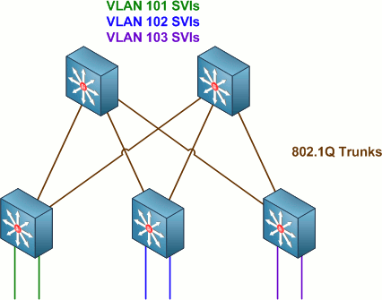
Routed SVIs (VLAN interfaces) configured on the distribution switches serve as end hosts' default gateways. This design works well enough, but does not provide true load balancing across access-distribution links due to L2 topology limitations (i.e. Spanning Tree blocking).
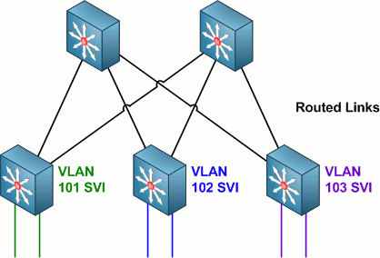
Then, along came multilayer switches like the Catalyst 3550 and 3560/3750, which made it possible to extend layer three functionality down to the access layer. The major benefits of such a design were the possibility of true equal cost path load-balancing across access-distribution links and faster failover times.
A third, recently developed access edge design employs virtual switches and multi-chassis link aggregation at the distribution edge. However, we'll only be looking at the first two designs mentioned in this article.
Of the two designs discussed above, the latter is generally preferred. However, many organizations find themselves bound to the layer two design in order to support legacy systems which require a contiguous L2 domain throughout large portions of the network. Such examples might include legacy "fat" wireless access points, security devices, HVAC sensors, and so on. In these cases, many organizations opt to implement a hybrid design which is able to provide L2 connectivity where required and L3 connectivity where possible.
A Hybrid Approach
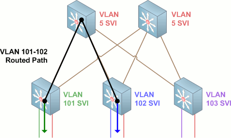
We can support both L2 and L3 connectivity at the access layer by implementing point-to-point links within VLANs on the access-distribution IEEE 802.1Q trunk links and relocating SVIs for the routed VLANs down to the access layer.
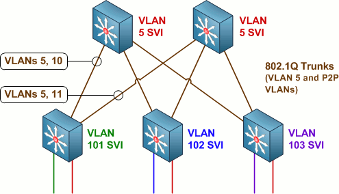
In the above topology, VLANs 101, 102, and 103 each terminate on their respective access switches. VLAN 5 is carried through the 802.1Q trunks up to the distribution layer where it can span multiple access switches. VLANs 10 and 11 each serve as independent point-to-point links (configured with an IPv4 /31) between the first access switch and either of the two upstream distribution switches. Both of the other access switches also have point-to-point VLANs configured to the distribution switches, for a total of six point-to-point links between the access and distribution layers.
A configuration on the leftmost access switch in the above example might look like this:
interface FastEthernet0/1
 description User Workstation
 switchport access vlan 101
 switchport mode access
!
interface FastEthernet0/2
 description Legacy L2 Access Device
 switchport access vlan 5
 switchport mode access
!
...
!
interface GigabitEthernet0/1
 description Uplink to Distribution Switch A
 switchport trunk encapsulation dot1q
 switchport trunk allowed vlan 5,10
 switchport mode trunk
!
interface GigabitEthernet0/2
 description Uplink to Distribution Switch B
 switchport trunk encapsulation dot1q
 switchport trunk allowed vlan 5,11
 switchport mode trunk
!
interface Vlan10
 description Point-to-Point Subnet for Distribution Switch A
 ip address 10.0.0.2 255.255.255.254
 ipv6 address 2001:db8:0:10::2/64
!
interface Vlan11
 description Point-to-Point Subnet for Distribution Switch B
 ip address 10.0.0.4 255.255.255.254
 ipv6 address 2001:db8:0:11::2/64
!
interface Vlan101
 description User Access VLAN
 ip address 10.0.101.1 255.255.255.0
 ipv6 address 2001:db8:0:65::1/64
!
router ospf 1
 router-id 172.18.0.101
 network 0.0.0.0 0.0.0.0 area 1
VLAN 5 traffic from one access switch to another is switched into the distribution layer and back down, never leaving VLAN 5. The path from source to destination is a single hop.
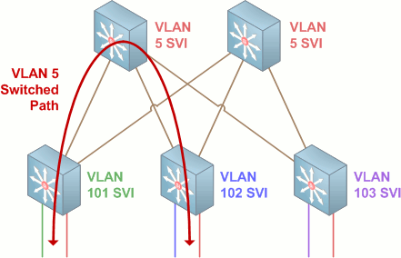
Traffic from VLAN 101 to VLAN 102 is removed from the access VLAN and routed out the SVI on the access switch. From there it is routed via the point-to-point VLAN in the trunk up to the distribution switch, and via a second point-to-point link down to the access switch for VLAN 102. The path from source to destination is three hops in length.
Questions Raised in Previous Comments
Why not simply go pure L3 links to the access edge?
If you can, do it! Again, this design is intended for situations where there still exists a requirement for L2 access between points within the access layer.
How well will this scale?
If implemented properly, very well. VLAN IDs used for access layer SVIs can be reused in a standard template, such that e.g. VLAN 101 is for workstations, VLAN 102 is for wireless APs, etc. Only the IP subnets need be unique.
This design seems too complex to manage and troubleshoot.
If you can manage a layer two network and you can manage a layer three network, you can manage this design. If you can't manage either of the first two networks, it's time to hit the books or look for a new job.
Vendor X doesn't recommend this design.
That's because this isn't an ideal solution, as already stated. The ideal solution is to remove the requirement for L2 access at the edge. Network design is a compromise between the ideal and the practical, heavily in favor of the practical.
A loop within the layer two topology can still bring down the network.
Again, this solution does not try to remove the downsides of a layer two topology. It simply allows us to take advantage of the benefits of a layer three access edge where we can. To remove the STP limitations, remove the need for L2 access.
It is also worth noting that while STP runs on the point-to-point VLANs between the access and distribution layers, these links by definition cannot form a loop (erroneous configuration issues aside).
Users will want to move among access blocks and keep their IP address.
Practical impediments to the roaming of wired clients aside, only the L2 VLAN(s) (VLAN 5 in the example above) would support this. Generally speaking, end users should always reside on the VLANs terminated on access layer switches. Further, it is up to your organization, not your network design, to decide on and enforce network policy.
How should VTP domains be arranged?
Unless you have a very good reason to use VTP, don't. Still, if you feel compelled to employ VTP, do so exercising the cautions you would on an all-L2 access layer design.
Posted in Design
Comments
February 9, 2011 at 4:31 a.m. UTC
The biggest drawback I see (and mentioned in the previous post) is the high cost of using an IP Services image on every access switch (in Cisco land). You can mitigate it somewhat by using stub routing with EIGRP, but you would lose the ability to have routed multicast with this design.
February 9, 2011 at 7:14 a.m. UTC
Great article, thanks.
I had been planning on keeping L2 links between access and distribution, but I may change it up. I'm having a hell of a time with Cisco/Extreme RSTP interop... If anyone has experience with this, let me know! OSPF would be much easier.
February 9, 2011 at 9:16 a.m. UTC
Hey Strech, nice diagrams and good article as usual!
The only issue I see is that in the event of for example the link between Access-switch-with-101 and the left Core switch, failing is that you get a significant amount traffic transiting one of the other access switches. HSRP, which I assume you have configured on the Core-switches for Vlan 5, has no clue that a link has failed and no HSRP-switchover will occur.
If the network is under heavy load, you will most likely have congestion on one of the the other access-switches uplinks. I.e. a failure on one access switch will potentially impact the other access switches.
Another way of doing it is provisioning a Etherchannel between the Core switches, manipulate STP to make that the preferred path (should be by default) and upgrade that link if you are short on bandwidth.
Hope that makes sense!
Regards,
Fredrik
February 9, 2011 at 3:43 p.m. UTC
Excellent followup.
I think the "A loop within the layer two topology can still bring down the network" people are referring to using STP rather than PVST or MST. In that case, a loop on the L2 network could put the "uplink" port (rather than just that port on vlan 5) into blocking mode, effectively taking down the routed link with it.
The solution to this is to be smart about STP and use PVST or MST.
February 9, 2011 at 3:54 p.m. UTC
Another followup after the last comment:
1) Might be a good idea to change the very first graphic to using L2-switch icons for the 3 access switches. This would help drive home the point that those devices don't do any L3 stuff.
2) I'm pretty sure this is the exact same model that my university campus uses. I also know that they "manage" the >4k line config files by using Perl scripts to add/remove vlans, move stuff around, etc. Having a programmatic system in place to make sure changes are propogated properly is definitely a requisite for this design to scale well.
3) Users shouldn't be using IP-addresses! Last semester we renumbered our printers to be on a rfc1918 space. Since most computers used hostnames all we had to do was update a DHCP entry, a DNS entry, and reboot the printer.
IP ADDRESSES AREN'T STATIC, THIS IS WHY WE HAVE DNS!
February 9, 2011 at 5:49 p.m. UTC
There is yet another way?
With the layer 2 approach you can almost get 'true' load-balancing and eliminate good old STP as long as the Vlan is only on a single access switch or 'daisy-chained' access switches.
As long as the Vlan from one core switch to the other is via the access switch then you do not need STP, so both uplinks are then active. By all means if you want to use STP then you could use it in case of mis-configurations? I would also consider using Etherchannel on the uplinks.
Configure GLBP on both core switches and you will pretty much get 'true' load-balancing.
BTW This is how I have designed my LAN Network to pretty much eliminate STP and use all active uplinks to the access switches.
CheerZ
February 10, 2011 at 5:37 a.m. UTC
Hey Jeremy,
As discussed in the previous post on this topic, I often implement a similar design. I found it to be extremely useful in implementing certain designs.
The most common use I have for this is when deploying colo provider TOR switching. It is our standard policy is to terminate the L3 directly onto the switch that the server plugs into. In this scenario, each server's next hop is the directly connected switch and packets follow the routing table flow.
When the customer has servers in multiple racks / TOR switches, either for expansion or for redundancy, the most sensible place terminate the layer 3 is on the common Distribution switches for the TOR.
I have found this design to be very flexible, and the only real drawback or complaint from other engineers is that this does require spanning-tree control across the switches. There are many ways to deal with this problem ;)
Kurt @networkjanitor
February 10, 2011 at 12:28 p.m. UTC
Hey Stretch, love the article, good work.
But I cannot see the advantage of the layer 3 links. Aside from taking up more IP space you have 3 hops via layer 3 as opposed to 2 hops if you had all your SVIs terminated on the distribution Switches.
Am I right?
Paul
February 10, 2011 at 3:42 p.m. UTC
@Paul: No. From the article:
The major benefits of such a design were the possibility of true equal cost path load-balancing across access-distribution links and faster failover times.
Cisco's Enterprise Campus Architecture design guide offers more detail on the benefits of a layer three access edge.
February 11, 2011 at 3:35 a.m. UTC
Great use of 2001:db8::/32 in documentation, Jeremy. :) I just found RFC 3849 while doing some casual studying.
I also love this solution for allowing both local and extended VLANs. This is going into my design documentation as something to look at the next time we have a network build.
Thanks for all the great work!
February 11, 2011 at 4:48 a.m. UTC
I prefer to use a stacked 3750 as the distribution, then connect each access switch to the distribution stack via a layer 2 trunk in an ether-channel.
The ether-channel will take care of load balancing (maybe not as well as OSPF but its still load balancing and you don't have one link being blocked via STP)
Spanning-tree is not really needed as there are no loops.
February 11, 2011 at 7:03 p.m. UTC
The biggest issue of this is the management hassle in terms of ACL. If all layers 3 are in distribution switch, you have usually manageable number of devices. Just imagine how many access switches you might have to manage?
February 11, 2011 at 7:08 p.m. UTC
@schilling: You can still apply ACLs for user subnets at the distribution layer the same as you would with a layer two access edge, just on different interfaces.
February 12, 2011 at 2:13 a.m. UTC
Well, how about these SVIs defined in access switch only. How about SVIs on a access switch belong to different departments?
February 12, 2011 at 2:18 a.m. UTC
@Schilling: You can easily match by source IP at the distribution layer just as you would with an L2 design. The only difference is that a packet sourced from an end host takes one routed hop (from the access switch to one of the upstream distribution switches) before encountering the ACL.
February 12, 2011 at 2:15 p.m. UTC
Hi Jeremy, Have you ever looked at TRILL or NX-OS Fabric Path to replace STP or L3 access layer? Recently I have been researching it for my data centers' next generation architecture. Didn't know if you've had any exposure to them. They seem to me to provide the best of both worlds (L2 & L3). Keep up the great work.
February 13, 2011 at 5:53 a.m. UTC
I use the exact same design that rakem described:
3750 stack for L3 distribution + LACP etherchannel to L2 access layer = No STP, decent load-balancing, simple design, low cost access layer
I described this model back in 2006 when we first started implementing it:
http://useopensource.blogspot.com/2006/07/cisco-campus-network-design-on-dime_19.html
February 13, 2011 at 8:00 a.m. UTC
could we get complete configuration for this topology to understand more depth how traffic flows .so i would request pls post complete configuration access layer as well as distribution layer switch
where VLAN 5 SVI configure at access layer switch or distribution layer switch
hoping you will clear my doubts
February 13, 2011 at 2:28 p.m. UTC
Nice post Jeremy. Just curious, why no L2 link between the Agg switches? In your examples VLAN 5 has a loop and will block one link at all but one Access switch. That one Access switch will also have the responsibility of handling HSRP between the Agg switches.
Cheers,
Brad
February 14, 2011 at 12:10 a.m. UTC
In our new design for our corporate office, we're using condensed core in the data center, with L2 vPCs from our Nexus to the access edge. Seems to be working pretty well, but it uses a lot of expensive ports on our 7Ks.
February 14, 2011 at 1:29 a.m. UTC
@Brad: I simply left out of the diagram anything beyond the immediate access layer, which might have been an oversight on my part. In this design it should be assumed that there is a layer two path among the distribution switches for VLAN 5.
February 14, 2011 at 3:35 p.m. UTC
I am seeing references to using 3750 stacks as two separate distribution switches and doing Etherchannel to them. When you stack 3750's they act as a single switch intelligence, meaning if the stack freaks out because of buggy code, for example, you have lost both of your 'redundant' switches. This has happened to me twice in two separate places, and will never happen again... I prefer two actual distribution switches, just as the article has described.
September 26, 2012 at 5:25 a.m. UTC
Neat article. I had to do this a while back when we were migrating some floors from an old building-wide-VLAN design. We ended up doing it this way so that equipment with static addresses (mostly printers) could be done outside of the outage window by the IT staff. This let us have both the old building wide VLAN and the per-floor VLAN run at the same time. As soon as all the printers were migrated we removed the building wide VLAN.
I think it's important to mention that the routed point-to-point VLANs should be costed higher than the other links. Otherwise if you have a break in your distribution layer link you risk traffic destined for the core hammering your access layer switches.
December 22, 2013 at 8:56 a.m. UTC
I was just thinking on how are you going to implement having the IP Telephony in this kind of design. What would be the best approach?
February 13, 2015 at 11:08 p.m. UTC
Hi,
Im trying to configure this for a college project, I'm struggling to get it to work, I'm having difficulty with configuring the distribution switches, Can somebody inform me on this please ? thanks
September 7, 2015 at 6:49 p.m. UTC
We're contemplating something like this as a migration path from a flat network.
We still need L2 functionality spanned across some or all access switches so whilst we can't escape L2 completely it would appear that RVI's with VSTP and OSPF would seem to give us the best compromise - L3 where we can do it, L2 where we need it.
If we have the requirement for L2 I'm not sure how we can do it any better?
July 4, 2016 at 11:33 p.m. UTC
Hello,
I tried setting up your config in packet tracer but I'm unable to get the user VLANs (VLAN 101, 102) to go across the Layer 2 trunk. Here is my "show int trunk":
Switch1#sho int trunk Port Mode Encapsulation Status Native vlan Fa0/24 on 802.1q trunking 99 Gig0/1 on 802.1q trunking 99
Port Vlans allowed on trunk Fa0/24 97,111 Gig0/1 97,112
Port Vlans allowed and active in management domain Fa0/24 97,111 Gig0/1 97,112
Port Vlans in spanning tree forwarding state and not pruned Fa0/24 97,111 Gig0/1 97,112
Please help, I just can't figure out how to get the Layer 3 links across the Layer 2 trunk to work.