The premiere source of truth powering network automation. Open and extensible, trusted by thousands.
NetBox is now available as a managed cloud solution! Stop worrying about your tooling and get back to building networks.
Dynamic Failover Between Two WAN Links
By stretch | Monday, August 29, 2011 at 2:04 a.m. UTC
Today we'll look at a common scenario in which a single small site has two physical connections to the outside world: a private WAN link to a VoIP provider's MPLS cloud used to carry voice traffic, and a business-class broadband connection (e.g. cable, DSL, FiOS, etc.) used for direct Internet access. We want to enable dual failover for these links so that the broadband link can carry voice traffic in the event that the MPLS link fails, and so that the MPLS link can carry Internet-bound traffic in case the broadband link fails.
Topology
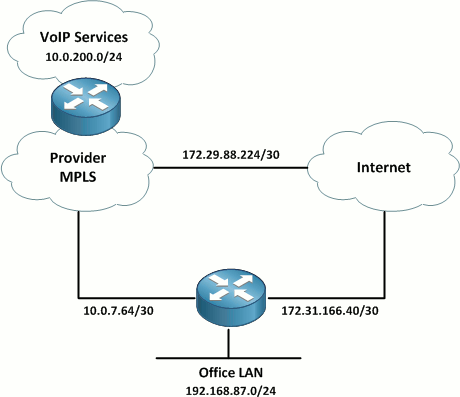
A local service provider has installed a 3 Mbps bonded T1 link to the site from its MPLS cloud to carry traffic to its VoIP services subnet (10.0.200.0/24). A dedicated circuit is necessary to support the QoS controls needed ensure acceptable voice call quality. The other link is a business-class broadband Internet circuit which is used for general Internet connectivity. BGP is running between the provider and customer site to advertise the relevant prefixes. A static default route has been configured on the customer router to direct all other traffic out the broadband link.
Note: The 172.16.0.0/12 space is used to represent public Internet addressing for the purposes of this lab.
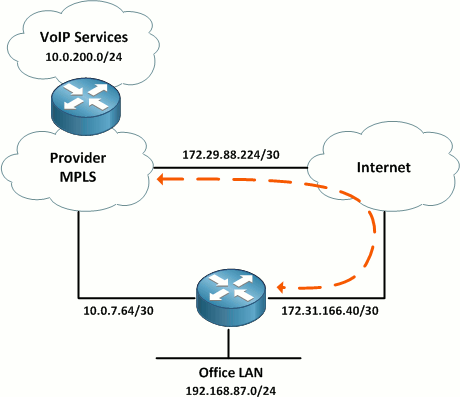
Failover from MPLS to Internet
Our first task for this component of the configuration is to build a VPN between the customer site and the VoIP provider across the public Internet. For this lab, we'll configure a route-based IPsec VPN as discussed in Policy-Based vs Route-Based VPNs: Part 2. The tunnel will be addressed out of the provider's IP space with 10.4.87.0/30. The relevant configuration on the customer router is below. (Obviously, the provider's VPN router needs to be configured similarly.)
crypto keyring Tunnel
  pre-shared-key address 172.31.166.42 key MySecretKey
!
crypto isakmp policy 10
 encr aes 256
 authentication pre-share
 group 5
crypto isakmp profile Tunnel
   keyring Tunnel
   match identity address 172.31.166.42 255.255.255.255
!
crypto ipsec transform-set ESP-AES256-SHA1 esp-aes 256 esp-sha-hmac
!
crypto ipsec profile Tunnel
 set transform-set ESP-AES256-SHA1
!
interface Tunnel0
 ip address 10.4.87.2 255.255.255.252
 tunnel source FastEthernet0/0
 tunnel destination 172.31.166.42
 tunnel mode ipsec ipv4
 tunnel protection ipsec profile Tunnel
BGP is running across the MPLS link, so we'll need to spin up a second BGP adjacency over the new VPN tunnel. Here's the relevant BGP configuration, with the new additions highlighted:
router bgp 65087
 bgp log-neighbor-changes
 neighbor 10.0.7.65 remote-as 65000
 neighbor 10.4.87.1 remote-as 65000
 !
 address-family ipv4
  neighbor 10.0.7.65 activate
  neighbor 10.0.7.65 soft-reconfiguration inbound
  neighbor 10.4.87.1 activate
  neighbor 10.4.87.1 soft-reconfiguration inbound
  no auto-summary
  no synchronization
  network 192.168.87.0
 exit-address-family
There's one caveat here: Both routes between the provider and the customer site will appear equally preferable with the current configuration in place. We want the BGP routers to prefer the direct MPLS link whenever it is available, and only route traffic over the VPN link in a failover condition. We also want to ensure that we fail back over to the MPLS link when it comes back up.
Given the simplicity of our lab scenario, we can achieve this easily by associating a weight with the MPLS BGP neighbor. In a real-world design, a more complex tactic of preferring one route over the other may be employed.
router bgp 65087
 address-family ipv4
  neighbor 10.0.7.65 weight 100
Remember that this route preference must be enforced at both ends of the adjacency to prevent asymmetrical routing issues.
Testing
In a normal condition where both links are up, our MPLS link is the preferred path from the customer site to the VoIP services prefix:
CPE-Router# show ip route 10.0.200.0
Routing entry for 10.0.200.0/24
  Known via "bgp 65087", distance 20, metric 11
  Tag 65000, type external
  Last update from 10.0.7.65 00:02:36 ago
  Routing Descriptor Blocks:
  * 10.0.7.65, from 10.0.7.65, 00:02:36 ago
      Route metric is 11, traffic share count is 1
      AS Hops 1
      Route tag 65000
CPE-Router# traceroute 10.0.200.1 source f0/1

Type escape sequence to abort.
Tracing the route to 10.0.200.1

  1 10.0.7.65 4 msec 4 msec 4 msec
  2 10.0.7.2 [AS 65000] 8 msec *  4 msec
When the MPLS link or its associated BGP adjacency fails, the preferred route is lost, and the traffic path is switched over to the VPN:
CPE-Router# show ip route 10.0.200.0
Routing entry for 10.0.200.0/24
  Known via "bgp 65087", distance 20, metric 11
  Tag 65000, type external
  Last update from 10.4.87.1 00:00:03 ago
  Routing Descriptor Blocks:
  * 10.4.87.1, from 10.4.87.1, 00:00:03 ago
      Route metric is 11, traffic share count is 1
      AS Hops 1
      Route tag 65000
CPE-Router# traceroute 10.0.200.1 source f0/1

Type escape sequence to abort.
Tracing the route to 10.0.200.1

  1 10.4.87.1 36 msec 20 msec 8 msec
  2 10.0.7.2 [AS 65000] 16 msec *  12 msec
Note: When troubleshooting on the customer router, remember to source pings from the LAN interface to ensure that the far end device has a route back to the originating address.
Failover from Internet to MPLS
So far, we've established failover for our SP-provided VoIP services, but what about Internet access? Provided that our MPLS connection to the VoIP provider includes access to the public Internet, we want to be able to fail over to it for Internet access in the event our direct broadband Internet link fails.
Our first step is to have the provider include a default route in their BGP advertisements from the MPLS router. (Advertising a default route over the VPN adjacency wouldn't make any sense because the adjacency itself is already reliant on Internet access.) The BGP-learned default route won't take any immediate effect because our static default route on the customer router takes precedence (static routes have an administrative distance of 1, versus BGP routes' AD of 20).
CPE-Router# show ip bgp neighbor 10.0.7.65 received-routes
BGP table version is 23, local router ID is 192.168.87.1
Status codes: s suppressed, d damped, h history, * valid, > best, i - internal,
              r RIB-failure, S Stale
Origin codes: i - IGP, e - EGP, ? - incomplete

Network          Next Hop            Metric LocPrf Weight Path
r  0.0.0.0          10.0.7.65                0             0 65000 ?
*  10.0.7.0/30      10.0.7.65                0             0 65000 ?
*  10.0.200.0/24    10.0.7.65               11             0 65000 ?

Total number of prefixes 3
CPE-Router# show ip bgp neighbor 10.4.87.1 received-routes
BGP table version is 23, local router ID is 192.168.87.1
Status codes: s suppressed, d damped, h history, * valid, > best, i - internal,
              r RIB-failure, S Stale
Origin codes: i - IGP, e - EGP, ? - incomplete

Network          Next Hop            Metric LocPrf Weight Path
*  10.0.7.0/30      10.4.87.1                0             0 65000 ?
*  10.0.200.0/24    10.4.87.1               11             0 65000 ?

Total number of prefixes 2
The r in the first BGP table above indicates a RIB failure caused by the static default route; this is what we want to see.
Next, since we aren't running a dynamic routing protocol across the broadband Internet link, we need a way to intelligently remove our static default route in case the Internet link fails. This will happen automatically if the physical link is lost and the interface transitions to a down state, but we'd like something more robust (particularly because broadband connections are often terminated on a CPE device separate from the router). We can configured IP SLA tracking to one or more destinations on the Internet to dynamically track our reachability out the Internet link.
In the example below, we configure an ICMP echo (ping) tracker to 8.8.8.8 (which belongs to Google's public DNS service) with a frequency of ten seconds.
ip sla 10
 icmp-echo 8.8.8.8 source-interface FastEthernet0/0
 frequency 10
ip sla schedule 10 start-time now
!
track 1 rtr 10
Finally, we associate our static default route with the new tracked object:
ip route 0.0.0.0 0.0.0.0 172.29.88.225 track 1
We can verify the status of the tracked object with the command show track:
CPE-Router# show track 1
Track 1
  Response Time Reporter 10 state
  State is Up
    1 change, last change 00:00:16
  Latest operation return code: OK
  Latest RTT (millisecs) 24
  Tracked by:
    STATIC-IP-ROUTING 0
Testing
In a normal condition, the tracked object is up and our static default route points out the Internet link as intended:
CPE-Router# show ip route 0.0.0.0
Routing entry for 0.0.0.0/0, supernet
  Known via "static", distance 1, metric 0, candidate default path
  Routing Descriptor Blocks:
  * 172.29.88.225
      Route metric is 0, traffic share count is 1
Should the tracked object fail for any reason, the static default route is automatically removed, and the default route learned from the VoIP provider via BGP is installed in its place:
CPE-Router# sh track 1
Track 1
  Response Time Reporter 10 state
  State is Down
    2 changes, last change 00:00:04
  Latest operation return code: Timeout
  Tracked by:
    STATIC-IP-ROUTING 0
CPE-Router# show ip route 0.0.0.0
Routing entry for 0.0.0.0/0, supernet
  Known via "bgp 65087", distance 20, metric 0, candidate default path
  Tag 65000, type external
  Last update from 10.0.7.65 00:00:09 ago
  Routing Descriptor Blocks:
  * 10.0.7.65, from 10.0.7.65, 00:00:09 ago
      Route metric is 0, traffic share count is 1
      AS Hops 1
      Route tag 65000
There are several caveats with this sort of failover design: For example, one must ensure that sufficient NAT translation (where applicable) firewalling is in place at both borders. But it can serve as a great low-cost solution for providing robust redundancy to small sites.
Posted in Routing
Comments
August 29, 2011 at 4:37 a.m. UTC
Hello, Jeremy!
Very good article. I have seen such setups in real life (not always the same, but similar).
I've been following you for a while. You make wonderful articles.
Let me propose one thing. We all got used to use RFC1918 address (10/8, 172.16/12 and 192.168/24) as inside networks. And it is ok. It doesn't look good to put this kind of addresses outside a customer's networks. For such examples special blocks of addresses were allocated (in reality not only addresses. There are even special DNS domains). All this staff you can find in RFC 5735.
To have more clear explanations we should use this kind of addresses.
With best regards and hope to see new articles.
Maxim Zimovets
August 29, 2011 at 2:08 p.m. UTC
Great article Stretch.
Thanks for that comment Maxim - I didn't know about those nets and that will make my documentation appear just a little bit more professional to my peers.
August 29, 2011 at 4:03 p.m. UTC
Why build a BGP neighbor across the tunnel? If the MPLS network dies, so do routes. Core devices would then forward all traffic to the default gateway, build a tunnel, etc.
August 29, 2011 at 5:36 p.m. UTC
Mr. Poplawski, I don't quite understad your point of view especially the last sentence: "Core devices would then forward all traffic to the default gateway, build a tunnel, etc." Can you please elaborate ?
August 29, 2011 at 10:10 p.m. UTC
@jbpoplawski: The SP routes need to be advertised to the customer site one way or another. BGP is one choice well-suited for the task; you could instead use another routing protocol or floating static routes on the CPE router.
Remember that the default route points out the Internet link, not the private point-to-point tunnel interface.
August 30, 2011 at 2:36 p.m. UTC
Regarding the internet failover, could you have a static /0 route on the VoIP provider link and two static /1 routes (0/1 & 128/1) assocated with the track object? I know OpenVPN uses that method to supercede the default route without needing to delete it.
August 30, 2011 at 7:09 p.m. UTC
No IPv6. sadface Great article. PDF saved, with many other gems from your fantastic blog. :)
September 16, 2011 at 4:08 p.m. UTC
Hello,
Nice article
I am looking forward to setup such a architecture. I am administering both ends of the WAN link and recently set up a business class Internet connection. I was just thinking of including the Tunnel interface to my core OSPF backbone with a higher OSPF cost than the WAN link instead of creating a second BGP session. There is already a single MP-BGP session with a remote MPLS router which is not directly terminating the WAN link. Is there any problem in this approach?
September 26, 2011 at 2:05 p.m. UTC
Interesting article, is there a reason you would do this vs using something like DMVPN? DMVPN adds spoke to spoke connectivity and a IMO simpler configuration.
October 10, 2011 at 9:37 a.m. UTC
I'm new to your web site. Let me tell you this, I'm very impressed and good job Jeremy.
Regards,
November 18, 2011 at 8:15 p.m. UTC
good job!
p.s. could you please share with us, how you draw topology or what kind of a soft u use?
thx
January 16, 2012 at 5:46 a.m. UTC
Hi Jeremy very good and impressive article, I like however I have an issue with this config shown below, when my primary internet is down my secondary is not taking over neither i have to reboot the primary SP ASA to bring back to normal, could you pls let me know where is the problem????
here is little bit more we have two different ISP with two ASA running with dynamic routing eigrp
Pri-ASA --
| CPE-3560
Sec-ASA --
CPE-3560
!
track 123 ip sla 1 reachability
ip routing
!
interface Vlan10
 ip address a.b.c.d 255.255.255.0
 no ip redirects
 ip policy route-map reroute_to_T1
 delay 20
!
router eigrp 100
 network 1.0.0.0
!
!
ip sla 1
 icmp-echo 2.2.2.2 (Secondary ASA int)
 timeout 1000
 threshold 2
 frequency 3
ip sla schedule 1 life forever start-time now
ip sla enable reaction-alerts
access-list 100 deny   ip host x y 0.0.0.255
access-list 100 permit ip host x any
access-list 100 permit ip host x any
access-list 100 deny   ip host x y 0.0.0.255
access-list 100 permit ip host x any
route-map reroute_to_T1 permit 10
 match ip address 100
 set ip next-hop 2.2.2.2 (Secondary ASA int)
!
!
!
these two routes are configured in Pri-ASA
!
route outside 0.0.0.0 0.0.0.0 a.b.c.d 1 track 1
route inside e.f.g.h 255.255.255.0 (vlan1 ip add configured on 3560) 1
!
these two routes are configured in Sec-ASA
!
route outside 0.0.0.0 0.0.0.0 i.g.k.l 1 track 1
route inside m.n.o.p 255.255.255.0 (vlan10 ip add configured on 3560) 1
November 5, 2012 at 12:03 p.m. UTC
Hi,
You may also check this video on what VoIP tunnel is. It is based on Ozeki Phone System XE and it fairly explains VoIP tunnel and VoIP:
http://www.ozekiphone.com/what-is-voip-tunnel-325.html
BR
February 26, 2016 at 12:04 p.m. UTC
this is good article,can you help me to understand how we can perform fail over from MPLS to VPN tunnel if there are packet drop observed on MPLS ?
June 27, 2016 at 10:16 p.m. UTC
Nice article!
The only thing I think that could be missing (keeping your style regarding scenario analysis as we are accustomed to see) is the consideration of flapping routes related to the IP SLA configuration.
You could add "delay up 30 down 30" to avoid the flapping route issue and consider a track list with multiple objects for redundancy.
Regards
July 18, 2016 at 3:13 p.m. UTC
Do you have the full configs for this scenario. If so, can you post or send it. Thanks..