The premiere source of truth powering network automation. Open and extensible, trusted by thousands.
NetBox is now available as a managed cloud solution! Stop worrying about your tooling and get back to building networks.
Policy-Based vs Route-Based VPNs: Part 1
By stretch | Monday, August 15, 2011 at 1:57 a.m. UTC
This is the first part of a two-part post that will compare and contrast policy-based VPNs and route-based VPNs. Policy-based VPNs encrypt and encapsulate a subset of traffic flowing through an interface according to a defined policy (an access list). The policy may dictate that only some or all of the traffic being evaluated is placed into the VPN. This type of VPN is often referred to as LAN-to-LAN when implemented on Cisco ASAs, and I have covered the ASA implementation before. This article examines the configuration of a policy-based VPN on Cisco IOS.
In contrast to a policy-based VPN, a route-based VPN employs routed tunnel interfaces as the endpoints of the virtual network. All traffic passing through a tunnel interface is placed into the VPN. Rather than relying on an explicit policy to dictate which traffic enters the VPN, static and/or dynamic IP routes are formed to direct the desired traffic through the VPN tunnel interface. IPsec quick and dirty provides a decent primer if you're not familiar with route-based VPNs on IOS.
The lab topology employed in this article is easily replicated using Dynamips or the community lab, and I encourage readers to play along in a lab of their own while reading. If you do, be sure to bookmark this VPN troubleshooting guide from Cisco before you begin. It can be a real time-saver should you run into a wall.
Topology
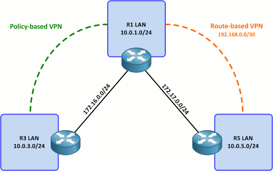
Our goal is to form two VPNs across the "public" network represented by the 172.16.0.0/15 space. (And before anyone brings up my New Year's pledge, I am planning to replicate both VPNs configurations using IPv6 in the future. I just wanted to keep the IP architecture as simple as possible for now since we're already dealing with two fairly complex topics.)
The first part of this article covers setting up a policy-based VPN between R1 and R3. The second part will cover the configuration of a route-based VPN tunnel between R1 and R5, and discuss some pros and cons to both approaches.
Step 1: Define an access list to match interesting traffic
This is the policy part of policy-based VPNs. We need to define an access list to match all the traffic we want to send through the VPN between the two routers. Every line in the access list will result in a bidirectional pair of IPsec security associations (SAs) between the VPN endpoints, so it's beneficial to be as succinct as possible when creating a policy.
For our purposes, we only need to match traffic between the two LANs attached to R1 and R3. Specifically, we need to match traffic from 10.0.1.0/24 to 10.0.3.0/24 on R1, and from 10.0.3.0/24 to 10.0.1.0/24 on R3. This results in two ACLs which mirror each other, one on either router.
R1
ip access-list extended R1_to_R3
 permit ip 10.0.1.0 0.0.0.255 10.0.3.0 0.0.0.255
R3
ip access-list extended R3_to_R1
 permit ip 10.0.3.0 0.0.0.255 10.0.1.0 0.0.0.255
Note that these ACLs must mirror each other exactly in order for the IPsec SAs to form correctly. This is easy when we only have one permit statement, but can become burdensome when dealing with numerous policy entries.
Step 2: Create a pre-shared key
To keep things simple, we'll configure the routers to authenticate one another (via ISAKMP) using a pre-shared key. In the real world, public key authentication provides much better security.
We'll create a keyring to hold our pre-shared keys, which are mapped by peer (public) IP address. R1 maps the key string MySecretKey to R3, and vice versa.
R1
crypto keyring VPN
  pre-shared-key address 172.16.0.3 key MySecretKey
R3
crypto keyring VPN
  pre-shared-key address 172.16.0.1 key MySecretKey
Step 3: Create an ISAKMP policy
Next we'll create an ISAKMP policy. This sets the parameters which will be used by the routers during IKE phase one, when the initial asymmetrically-encrypted ISAKMP SA is negotiated. The policy below employs 256-bit AES using pre-shared key authentication (from step two) and Diffie-Hellman group five.
This policy is applied identically to both routers.
R1 and R3:
crypto isakmp policy 10
 encr aes 256
 authentication pre-share
 group 5
Step 4: Create an ISAKMP profile
An ISAKMP profile is used to establish parameters for a particular ISAKMP peer by matching its outside IP address. We specify the keyring to be used for this peer so that the router knows how to locate the correct pre-shared key.
R1
crypto isakmp profile R1_to_R3
   keyring VPN
   match identity address 172.16.0.3 255.255.255.255
R3
crypto isakmp profile R3_to_R1
   keyring VPN
   match identity address 172.16.0.1 255.255.255.255
Step 5: Define an IPsec transform-set
Now that ISAKMP is out of the way, we move on to IPsec configuration, which is much less involved: We simply need to define an IPsec transform-set. A transform-set tells the router what protocol, encryption, and hashing algorithms to use when forming the IPsec SAs, as well as in which mode to operate (tunnel or transport) and a few other details. The line below defines a transform-set employing ESP with 256-bit AES and SHA-1 hashing (similar to our ISAKMP policy) in tunnel mode. Create the same transform-set on both routers.
R1 and R3
crypto ipsec transform-set ESP-AES256-SHA1 esp-aes 256 esp-sha-hmac
Step 6: Create and apply the crypto map
Finally, we tie together all of these pieces by creating a crypto map, which does a few things. In order of the config snippets presented below, these are:
- Matches "interesting" traffic based on the access list we created in step one
- Sets the remote peer to the outside IP address of the remote router
- Sets the transform-set we defined in step five
- Sets the ISAKMP profile we defined in step four
- Enables static reverse-route injection, which creates static routes for the remote networks specified by the matched access list
- Sets the administrative distance of the injected static routes to ten (optional)
After creating the crypto map, apply it to the appropriate interface on each router.
R1
crypto map Policy_VPN 10 ipsec-isakmp
 match address R1_to_R3
 set peer 172.16.0.3
 set transform-set ESP-AES256-SHA1
 set isakmp-profile R1_to_R3
 reverse-route static
 set reverse-route distance 10
!
interface FastEthernet0/0
 crypto map Policy_VPN
R3
crypto map Policy_VPN 10 ipsec-isakmp
 match address R3_to_R1
 set peer 172.16.0.1
 set transform-set ESP-AES256-SHA1
 set isakmp-profile R3_to_R1
 reverse-route static
 set reverse-route distance 10
!
interface FastEthernet0/0
 crypto map Policy_VPN
Our policy VPN configuration is complete! We can verify that the crypto map has injected a static route on R1 for the 10.0.3.0/24 network on R3. (Note that the static parameter of the reverse-route command causes the route to be injected even when the VPN tunnel is not established.)
R1# show ip route
Codes: C - connected, S - static, R - RIP, M - mobile, B - BGP
       D - EIGRP, EX - EIGRP external, O - OSPF, IA - OSPF inter area
       N1 - OSPF NSSA external type 1, N2 - OSPF NSSA external type 2
       E1 - OSPF external type 1, E2 - OSPF external type 2
       i - IS-IS, su - IS-IS summary, L1 - IS-IS level-1, L2 - IS-IS level-2
       ia - IS-IS inter area, * - candidate default, U - per-user static route
       o - ODR, P - periodic downloaded static route

Gateway of last resort is not set

172.17.0.0/24 is subnetted, 1 subnets
C       172.17.0.0 is directly connected, FastEthernet0/1
     172.16.0.0/24 is subnetted, 1 subnets
C       172.16.0.0 is directly connected, FastEthernet0/0
     10.0.0.0/24 is subnetted, 2 subnets
S       10.0.3.0 [10/0] via 172.16.0.3
C       10.0.1.0 is directly connected, Loopback1
Testing
Policy VPNs by nature are created on-demand when traffic which matches the associated policy (access list) is detected egressing an interface to which the crypto map is applied. Currently, there are no existing ISAKMP SAs:
R1# show crypto isakmp sa
IPv4 Crypto ISAKMP SA
dst             src             state          conn-id status

IPv6 Crypto ISAKMP SA
We can generate some traffic to trigger the creation of the VPN by performing a simple ping whose source and destination addresses are matched by the VPN policy:
R1# ping 10.0.3.1 source 10.0.1.1

Type escape sequence to abort.
Sending 5, 100-byte ICMP Echos to 10.0.3.1, timeout is 2 seconds:
Packet sent with a source address of 10.0.1.1
.!!!!
Success rate is 80 percent (4/5), round-trip min/avg/max = 1/3/4 ms
Notice that the first packet was dropped while the VPN was established. The next four pings succeeded, and we can verify that an ISAKMP SA was established. We can also verify the creation of IPsec SAs with the command show crypto ipsec sa.
R1# show crypto isakmp sa
IPv4 Crypto ISAKMP SA
dst             src             state          conn-id status
172.16.0.3      172.16.0.1      QM_IDLE           4003 ACTIVE

IPv6 Crypto ISAKMP SA
Successive pings will all succeed so long as the VPN tunnel doesn't time-out.
R1# ping 10.0.3.1 source 10.0.1.1

Type escape sequence to abort.
Sending 5, 100-byte ICMP Echos to 10.0.3.1, timeout is 2 seconds:
Packet sent with a source address of 10.0.1.1
!!!!!
Success rate is 100 percent (5/5), round-trip min/avg/max = 1/3/4 ms
That about wraps it up for simple policy-based VPNs. In part two, we'll look at the configuration of a comparable route-based VPN and examine the pros and cons of each approach.
Posted in Security
Comments
August 15, 2011 at 4:45 a.m. UTC
Nice post!
Why did you consider to use keyrings and Isakmp profiles instead of applying the config global?
August 15, 2011 at 7:16 p.m. UTC
Very well explained, keep up the good work!
August 16, 2011 at 11:03 a.m. UTC
Very usefull post. I have never known about reverse-route static directive.
I'm waiting for second part.
Thanks.
August 16, 2011 at 9:36 p.m. UTC
I don't understand how you can ping the 10.0.3.1 if it wasn't defined/configured. Did you create a subinterface for this network?
By the way, congratulations for the post!
August 17, 2011 at 1:23 a.m. UTC
@Rodrigo: 10.0.3.1/24 was assigned to a loopback interface on R3 to emulate an internal network. This is common practice when dealing with lab topologies which aren't quite as big as a real network.
I've posted the finished configs from all three routers at the end of part two, which might help.
August 17, 2011 at 2:12 p.m. UTC
Thanks!
August 21, 2011 at 5:04 p.m. UTC
Nice write up. I will like to read more from you, Thanks
August 22, 2011 at 2:56 a.m. UTC
Hi Sir Jeremy,
Match identity address 172.16.0.3 255.255.255.255 >> Why is the SM set to /32 since in the diagram is /24?
August 22, 2011 at 3:22 p.m. UTC
Hi Stretch,
Just wanted to say i've read many of your new posts as well as the old ones. They are all really well written, straight to the point, perfectly formatted and diagrams top notch.
I really like the way you represent code examples. Makes your posts so easy to read. Thank you for all the time and effort you put into these.
cheers,
jimmy
August 22, 2011 at 3:45 p.m. UTC
Good Job, Excellent
August 25, 2011 at 8:27 a.m. UTC
very nice post....keep up the good work..this clears the concept in juniper firewall world also
November 15, 2011 at 6:37 a.m. UTC
Thank you Jeremy.
November 30, 2011 at 12:38 p.m. UTC
Really awesome explanation. loved reading it.
April 2, 2013 at 4:58 a.m. UTC
Hi there,
In the last part of this guide, you state "We can generate some traffic to trigger the creation of the VPN by performing a simple ping whose source and destination addresses are matched by the VPN policy" and "Successive pings will all succeed so long as the VPN tunnel doesn't time-out". How can you open a tunnel and keep it open?
Thanks!
May 6, 2013 at 12:12 p.m. UTC
Hi,
Nice post, a quick question will ASA support both policy and route based vpn?
Thanks,
June 18, 2013 at 12:09 p.m. UTC
Very good information. Thanks
May 13, 2014 at 11:48 p.m. UTC
Precise and clear post.
January 25, 2016 at 6:58 a.m. UTC
Nice post Jeremy
March 15, 2016 at 8:50 p.m. UTC
Your post is remarkable helpful everyone like me. I am trying to configure DHCP relay agent throgu IP-Sec VPN by using cisco Router(881). I am facing difficulties. If you have any example please let me know. That would be a great help for me.
July 21, 2016 at 1:14 p.m. UTC
Very helpful!