The premiere source of truth powering network automation. Open and extensible, trusted by thousands.
NetBox is now available as a managed cloud solution! Stop worrying about your tooling and get back to building networks.
Deploying Datacenter MPLS/VPN on Junos
By stretch | Tuesday, April 15, 2014 at 1:17 a.m. UTC
One of my recent projects has been deploying an MPLS/VPN architecture across a pair of smallish datacenters comprised entirely of Juniper gear. While I'm no stranger to MPLS/VPN, I am still a bit green to Junos, so it was a good learning exercise. My previous articles covering MPLS/VPN on Cisco IOS have been fairly popular, so I figured it would be worthwhile to cover a similar implementation in the Juniper world.
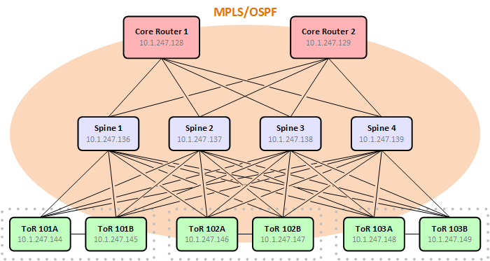
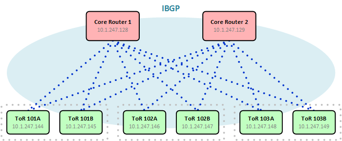
For our datacenters, we decided to implement a simple spine and leaf topology with a pair of core routers functioning as IBGP route reflectors and a pair of layer three ToR switches in each server rack. The spine is comprised of four layer three switches which run only MPLS and OSPF; they do not participate in BGP.
This article assume some basic familiarity with MPLS/VPN, so if you're new to the game, consider reading through these previous articles for some background before continuing:
Building the MPLS Underlay
Implementing vanilla MPLS with LDP is pretty straightforward: Enable MPLS and LDP on all your P interfaces, turn up OSPF, and do some quick sanity-checking. (Of course, merely deploying frame-mode MPLS doesn't buy us anything: This is just our first step.)
Begin by adding the MPLS address family to all interfaces which will carry MPLS-encapsulated traffic. You might opt to define an interface-range for all P interfaces depending upon the density of your network.
Router# set interface <interface> family mpls
We also need to add these same interfaces under the MPLS protocol configuration:
Router# set protocols mpls interface <interface>
This might seem redundant, but you can think of it this way: The first command enables the forwarding plane to accept MPLS-encapsulated packets, whereas the second command enabled MPLS processing and table generation within the control plane.
While we're add it, we need to enable LDP as well. LDP handles the mapping of labels to forwarding equivalence classes and the exchange of labels with neighboring routers. (LDP is not to be confused with the unrelated layer two signaling protocol LLDP.)
Router# set protocols ldp interface <interface>
LDP relies on an IGP routing table to generate and map labels, so let's add OSPF next. The following example shows a minimal configuration on a ToR switch:
ospf {
    reference-bandwidth 100g;
    area 0.0.0.0 {
        interface xe-0/0/0.0 {
            interface-type p2p;
        }
        interface xe-0/0/1.0 {
            interface-type p2p;
        }
        interface xe-0/0/2.0 {
            interface-type p2p;
        }
        interface xe-0/0/3.0 {
            interface-type p2p;
        }
        interface lo0.0 {
            passive;
        }
    }
}
Believe it or not, that should be enough to get a bare-bones MPLS network up and running. A few simple commands will verify our configurations:
ToR-101A> show mpls interface
Interface        State       Administrative groups (x: extended)
xe-0/0/0.0       Up
xe-0/0/1.0       Up
xe-0/0/2.0       Up
xe-0/0/3.0       Up
ToR-101A> show ldp interface
Interface            Label space ID        Nbr count   Next hello
xe-0/0/0.0           10.1.247.144:0         1           3
xe-0/0/1.0           10.1.247.144:0         1           0
xe-0/0/2.0           10.1.247.144:0         1           2
xe-0/0/3.0           10.1.247.144:0         1           0
ToR-101A> show ldp neighbor
Address            Interface          Label space ID         Hold time
10.1.244.64      xe-0/0/0.0         10.1.247.136:0         12
10.1.244.66      xe-0/0/1.0         10.1.247.137:0         12
10.1.244.68      xe-0/0/2.0         10.1.247.138:0         11
10.1.244.70      xe-0/0/3.0         10.1.247.139:0         13
ToR-101A> show ospf neighbor
Address          Interface              State     ID               Pri  Dead
10.1.244.64    xe-0/0/0.0             Full      10.1.247.136   128    34
10.1.244.66    xe-0/0/1.0             Full      10.1.247.137   128    37
10.1.244.68    xe-0/0/2.0             Full      10.1.247.138   128    37
10.1.244.70    xe-0/0/3.0             Full      10.1.247.139   128    35
Great! We've got MPLS adjacencies established from this ToR switch to each of the four spine switches. Notice that although the TCP-based LDP adjacencies are formed between the physical interface addresses, the label space identifiers are taken from each switch's loopback address.
This completes the configuration on the spine switches. The remainder of work to be done applies to the core routers and ToR switches only.
MP-BGP Configuration
Multi-protocol BGP is the heart of an MPLS/VPN network. PE routers use it to exchange routes and VPN information with one another. MP-BGP configuration can be a bit intimidating to those not familiar with it, but configuring basic adjacencies takes little effort.
First, we configure our autonomous system number. While it's entirely possible to run MPLS/VPN across multiple autonomous systems, to keep things simple we're using a single AS here.
Router# set routing-options autonomous-system 65000
Next, we enable MP-BGP on each ToR switch and configure the loopback IP addresses of the two core routers as peers.
protocols {
    bgp {
        group Internal {
            type internal;
            family inet-vpn {
                unicast;
            }
            neighbor 10.1.247.128 {
                description Core-01;
            }
            neighbor 10.1.247.129 {
                description Core-02;
            }
        }
    }
}
The command type internal sets the adjacency type to IBGP. family inet-vpn unicast enables the transport of IPv4 routes. (I've intentionally neglected IPv6 here in the interest of brevity, but its configuration is similar.)
MP-BGP is configured on the core routers the same as on the ToR switches with one very important addition: A cluster ID. This instructs the core routers to function as IBGP route-reflectors, forwarding routes learned from one ToR switch to all the others. The core router's loopback IP address is used as its cluster ID.
protocols {
    bgp {
        group Internal {
            type internal;
            family inet-vpn {
                unicast;
            }
            cluster 10.1.247.128;
            neighbor 10.1.247.144 {
                description ToR-101A;
            }
            neighbor 10.1.247.145 {
                description ToR-101B;
            }
            ...
        }
    }
}
Once BGP has been configured on both core routers and all ToR switches, use show bgp summary to verify that the adjacencies have come up. If all neighbors seem to be stuck in active, check that their loopback addresses are being advertised via OSPF and that they can reach one another.
VRF Configuration
On Junos, a VRF is configured as a distinct type of routing-instance (literally, instance-type vrf). VRF configuration is where we assign logical interfaces, the VRF route distinguisher, and the route target import and export policies (which we'll add in the next step).
routing-instances {
    Development {
        instance-type vrf;
        interface vlan.100;
        route-distinguisher 65000:100;
        vrf-table-label;
    }
}
routing-instances {
    Production {
        instance-type vrf;
        interface vlan.200;
        route-distinguisher 65000:200;
        vrf-table-label;
    }
}
The line vrf-table-label at the end instructs the router to create an MPLS label for the VPN itself. This ensures that routes with a next-hop pointing to a directly attached multiaccess networks (for which the next-hop adjacency information isn't readily available) also receive routes.
If you're accustomed to building VRFs on Cisco IOS, the Juniper approach will seem a bit verbose. While it is possible to assign a single import RT and a single export RT without defining policies, they are mandatory when dealing with multiple RTs per VRF. First, we need to define and name each route target that we want to use:
policy-options {
    community RT-Development-Export members target:65000:100;
    community RT-Development-Import members target:65000:101;
    community RT-Production-Export members target:65000:200;
    community RT-Production-Import members target:65000:201;
    community RT-Internet-Export members target:65000:900;
    community RT-Internet-Import members target:65000:901;
}
Defining a pair of sequential route targets for each VRF allows for very scalable import and export control among many VRFs. For the purposes of this example though, we'll just focus on two.
First we'll define our import policy for the Development VRF. This policy matches all routes learned via BGP with at least one of the listed route targets (which you'll recall are simply BGP communities). All other routes are rejected.
policy-options {
    policy-statement Development-Import {
        term Import {
            from {
                protocol bgp;
                community [ RT-Development-Export RT-Development-Import RT-Internet-Export ];
            }
            then accept;
        }
        term Reject {
            then reject;
        }
    }
}
Our export policy is configured similarly. In this example, we're exporting only directly connected routes. Two route targets are applied to each route being exported: RT-Development-Export (for import by other instances of the Development VRF) and RT-Internet-Import (for import into the Internet VRF).
policy-options {
    policy-statement Development-Export {
        term Export {
            from protocol direct;
            then {
                community add RT-Development-Export;
                community add RT-Internet-Import;
                accept;
            }
        }
        term Reject {
            then reject;
        }
    }
}
Don't forget to apply the policies to the VRF:
routing-instances {
    Development {
        instance-type vrf;
        interface vlan.400;
        route-distinguisher 65000:100;
        vrf-import Development-Import;
        vrf-export Development-Export;
        vrf-table-label;
    }
}
Once all VRFs have been configured at the appropriate points throughout the network, MP-BGP will facilitate the exchange of routes among them. You can verify the routes within a certain VRF with the command show route table <VRF>.
One last tip: It's likely that you'll want to run BGP or an IGP within a VRF at the edge of your MPLS network. To do so, simply configure the protocol as you normally would under the routing-instance hierarchy, like so:
routing-instances {
    Internet {
        routing-options {
            aggregate {
                route 10.1.244.0/22;
            }
        }
        protocols {
            bgp {
                group Legacy {
                    type external;
                    export [ My-Routes ];
                    neighbor 192.0.2.1 {
                        description ISP-A;
                    }
                    neighbor 192.0.2.5 {
                        description ISP-B;
                    }
                }
            }
        }
    }
}
Comments
April 15, 2014 at 8:53 p.m. UTC
It seems that Juniper allows to use a structure like { and } for your configuration. I very much like the idea. Once I'm done with Cisco I will have a look on Juniper's solutions.
April 17, 2014 at 8:31 a.m. UTC
Can you tell which gear you're using for spine / ToR switches? Also, are you using L2VPN/VPLS instances?
April 17, 2014 at 11:57 a.m. UTC
All of the spine and ToR switches are currently QFX3500s, although we're considering moving to QFX5100 once the bugs have been ironed out. We've had no need for L2VPN.
April 17, 2014 at 8:19 p.m. UTC
I love Juniper! It's really nice if you have any programming background.
April 21, 2014 at 3:36 p.m. UTC
I'm glad you are taking the deep dive plunge into Juniper. Once I started using Junos, I found it hard to go back to Cisco without feeling like I was taking a step back. I love the flexibility of their routing policy language. The QFX5100's are great switches you will like them, especially once they start running kvm this June. Then you can virtualize Junos and upgrade between versions without any downtime.
We are also using a similar MPLS setup, as well as VPLS for certain things like extending Internet pops. I was wondering; this looks pretty much green field, is this a new data center or were you retrofitting an existing one?
April 30, 2014 at 3:45 p.m. UTC
I needed to add:
set protocols bgp group Internal local-address [loopback ip]
May 5, 2014 at 5:28 p.m. UTC
Great article.. can you add other details to the design how this datacenter is connected to edge of the network ?
May 6, 2014 at 12:52 a.m. UTC
So when a server on a ToR needs to talk to other ToR does data plane traffic goes all the way to one of the core router?
May 6, 2014 at 2:59 p.m. UTC
@chandu: Edge connectivity is unrelated to the MPLS/VPN design; that's all external routing.
@krishna: No. Inter-rack traffic is carried by MPLS via the spine switches.
August 1, 2014 at 10:06 p.m. UTC
Hi Jeremy! Why you did not use any of SDN solutions, like VMWare NSX or Alcatel-Lucent Nuage? They provide similar functionality and you can give customers to create their own networks?
August 23, 2014 at 5:27 p.m. UTC
How this is related to Data center, as reading the article , i see this is common MPLS or l3vpn deployment. I am not getting the data center concept here as i find this is same as normal mpls l3vpn deployment using Route Reflector.
August 24, 2014 at 9:58 p.m. UTC
It's useful in multi-tenant Datacenter where you use the ToR switches as 1st hop gateway for VMs while retaining the logical isolation.
January 16, 2015 at 6:33 p.m. UTC
Jeremy, I really didn't understand the purpose of running MPLS in Leaf & Spine architect, and what would the latency look like for all east and west traffic?
January 16, 2015 at 6:40 p.m. UTC
Jeremy, Can you please explain why you running MPLS in Leaf & Spine architect? and what does the Letancy look like? The reason I am asking is that, we do leaf and spine due to low latency and more east west traffic Like Hadoop.