The premiere source of truth powering network automation. Open and extensible, trusted by thousands.
NetBox is now available as a managed cloud solution! Stop worrying about your tooling and get back to building networks.
Simultaneous Tunneled and Native Internet Access
By stretch | Tuesday, September 4, 2012 at 12:19 a.m. UTC
Suppose you have a number of branch sites which need to connect to a hub site. Each branch site has a private dedicated circuit as its primary path and a routed VPN tunnel carried over a business-class broadband circuit as its secondary circuit.
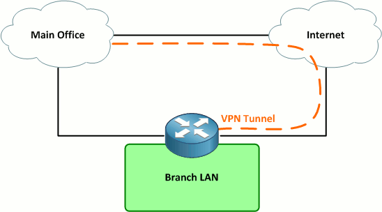
Under normal conditions, all traffic from the site traverses the dedicated circuit. Should the dedicated circuit fail, all traffic (including Internet traffic) traverses the VPN tunnel over the Internet back to the main site. Internet traffic is routed via the main site rather than directly out to the Internet to ensure that is passes through a content filtering mechanism.
This design is fairly simple, but what if we need to provide Internet access for a guest wireless network as well? This guest traffic can not, for security reasons, be routed through the main office; it must be routed directly out to the Internet via the broadband circuit.
The first implication of this new requirement is that we will need two default routes: One for internal corporate traffic to follow back to the main site, via either the dedicated circuit or the VPN tunnel, and one for the guest network to follow directly out to the Internet. We can leverage VRF lite on Cisco IOS to accomplish this.
First, let's define our interfaces on the branch router:
- Gi0/0.10 - Corporate network (VLAN 10)
- Gi0/0.20 - Guest network (VLAN 20)
- Gi0/1 - Private MPLS connectivity to main office
- Gi0/2 - Broadband Internet access
- Tunnel0 - Backup VPN tunnel to main office
We'll create a VRF named Internet to hold the guest network and Internet interfaces and a default route. Corporate network routes will be kept in the global table. (This may be the inverse of what you would expect when employing a VRF, but it works quite well.)
ip vrf Internet
!
interface GigabitEthernet0/0
 no ip address
!
interface GigabitEthernet0/0.10
 description Corporate LAN
 encapsulation dot1Q 10
 ip address 10.8.42.1 255.255.255.0
!
interface GigabitEthernet0/0.20
 description Guest Wireless
 encapsulation dot1Q 20
 ip vrf forwarding Internet
 ip address 192.168.1.1 255.255.255.0
!
interface GigabitEthernet0/1
 description Private Circuit
 ip address 10.8.0.26 255.255.255.252
!
interface GigabitEthernet0/2
 description Broadband Internet
 ip vrf forwarding Internet
 ip address 192.0.2.84 255.255.255.0
!
interface Tunnel0
 description VPN Tunnel to Main Office
 ip address 10.16.0.26 255.255.255.252
 tunnel source GigabitEthernet0/2
 tunnel destination 174.143.213.184
 tunnel protection ipsec profile VPN
Assume that a default route is being advertised via BGP over the private circuit, and a floating static default route has been configured pointing out the VPN tunnel in the global table. We just need to configure a static default route in the Internet VRF:
Router(config)# ip route vrf Internet 0.0.0.0 0.0.0.0 192.0.2.1
There's one piece of configuration left to make: Since we assigned Gigabit0/2 to the Internet VRF, and Tunnel0 is being sourced from that interface, we need to explicitly source Tunnel0 from that VRF:
Router(config)# interface tunnel0
Router(config-if)# tunnel vrf Internet
This command instructs the router to follow the Internet VRF routing table to reach the tunnel endpoint. It does not affect the forwarding of traffic within the tunnel, which is kept in the default routing table. (To change the forwarding VRF, you would use the command ip vrf forwarding just as you would on a physical interface.)
Note: I've not included a complete configuration here: You would want to extend the interface configurations to employ NAT and probably some type of security control, such as IOS Zone-Based Firewall.
Posted in Design
Comments
September 4, 2012 at 1:13 a.m. UTC
Good article, I'm having fun and learning by going back in the archive of the site while waiting for new posts :)
One thing I've noticed at work is that when customer have this setup and their main site goes down they are a lot more frustrated then if they had a separate content filtering device at each site.
I know that it is a lot more expensive but if you only lose your main site instead of all of them isn't that better?
You have redundant connections at your branch offices. You then limit yourself to a single point of failure in that all traffic must go to the main site.
An addition or expansion to this might be that if the main site can't be reached that normal internet traffic be allowed out out of the broadband connection. If this is allowed by the rules of the organization and laws it has to follow. I don't think this would work for schools as they need to filter what their students can access.
September 5, 2012 at 8:47 p.m. UTC
Good article. I would normally accomplish this using Policy-based Routing. Any thoughts on pros/cons of either technique?
September 5, 2012 at 11:53 p.m. UTC
@Steven: As a rule, I avoid PBR wherever possible. In my experience it's rarely an elegant solution (and even more rarely thoroughly documented).
September 9, 2012 at 11:43 a.m. UTC
hi dear
thanx
topic is very very .... gooooooooooooooooooooooooood
September 13, 2012 at 8:09 a.m. UTC
This is great way of doing it. We have similar setup but for Guest/Visitor, we use route-map and next hop IP of the ISP default-gateway so that all guest/visitor traffic break out to the internet through local ISP without going through our core network. Furthermore, I have setup a bandwith limit and restricted them to limited amount of bandwidth that they get using traffic shapping policy.
October 18, 2012 at 1:54 p.m. UTC
There are other ways to accomplish this, but this is probabbly the cleanest and kills both the routing and security birds with one stone. It's simple and ensures that the guest users can't touch the corporate network.
The only thing different I'd probabbly do rather than using a floating static is peer the BGP peers over both links using two different loopbacks at the Main office router. Using the lower IP for the private circuit and the higher IP for the VPN tunnel. That way you will get identical BGP tables from the same peer on two different addresses. With identical parameters BGP will install prefixes learned from the lower IP address into the routing table. When the private circuit fails, those routes gets flushed and BGP will install the prefixes, including the default route, learned through the other peering. That way all your routes failover to the VPN tunnel, not just the default route.
October 30, 2012 at 2:17 p.m. UTC
Where is documented that the data license also includes IP SLA?
November 14, 2012 at 3:03 p.m. UTC
Good article.
However, our company uses ASAs everywhere, no routers. So we can't use VRF nor PBR.
November 21, 2012 at 6:18 a.m. UTC
good article...
I have a setup like this with 120+ sites.. I guess alot of us do.
Being busy and a dead-line (surprising) to implement Wireless controller + identity service engine from cisco, i've gone ahead and let the local DSL hand out the ip addresses to guests, that way they don't touch the corporate side at all.
they connect to ssid which is set to guest vlan and end of story.
no config :]
I've also natted all DSL modem/routers so I can access them from HQ in case I need to change something - hell i've even gone ahead and setup dynDNS on most of them, so i can access them as ny.mycompany.com , chicago.mycompany.com and so on, eventhough their public address changes.
pros: easy
cons: not alot of visibility of what they are doing.
January 21, 2013 at 9:28 p.m. UTC
Interesting design. That is what makes networking so awesome! So many ways of accomplishing the same things.
I used layer 2 VLAN Access Maps to restrict Guest Network Traffic from Corporate users...both directions. They are even NAT'd to a different public address so they they cannot SSH into our external devices. They in effect...follow the same default route...regardless of which network they are on. This enables us to ensure traffic is properly routed through our IPS's...firewall dynamic filters, etc...etc.
February 6, 2013 at 8:15 a.m. UTC
What would this look like with a crypto map vs the tunnel to establish the vpn tunnel?
February 17, 2013 at 11:19 p.m. UTC
Hi Jeremy
Thanks for the inspiration.
I used your example in different way. VRF is defined for tunnel and uses global ip routing table to forward packet for this tunnel.
michal
P.S. here is config:
ip vrf Client_A
interface Tunnel44 description ### Tunnel to Client_A for monitoring ### ip vrf forwarding Client_A ip address 10.44.44.1 255.255.255.252 tunnel source fa0 tunnel destination Public_IP_addesss_Client_A tunnel mode ipsec ipv4 tunnel protection ipsec profile IPSEC-PROFILE-VPN-SERVER exit
interface Fa0 description ### Public IP address ### ip address Public_IP_address ! no vrf