The premiere source of truth powering network automation. Open and extensible, trusted by thousands.
NetBox is now available as a managed cloud solution! Stop worrying about your tooling and get back to building networks.
MPLS VPN with Common Services
By stretch | Thursday, May 19, 2011 at 4:08 a.m. UTC
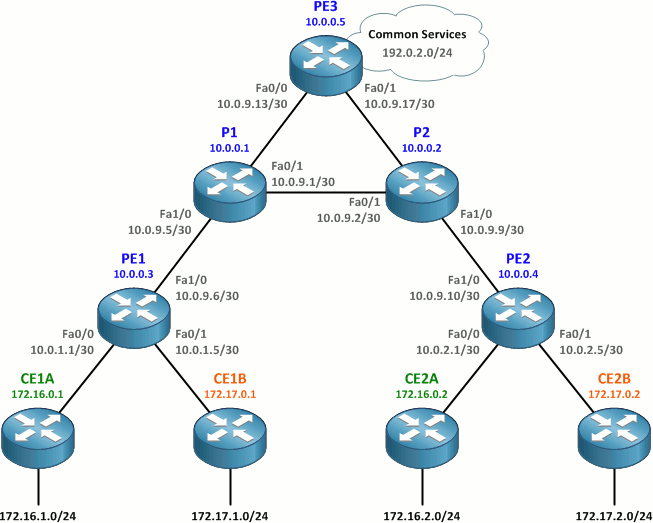
Earlier this week we looked at how to build a basic MPLS VPN to connect customer sites across a shared physical infrastructure while keeping different customers isolated from one another. (Read that article first if you haven't already.) Today we'll work on extending that network to introduce a common services VRF which will provide a number of shared services to all of the customer sites.
Here we've added a third PE router, PE3, to the topology taken from the prior article. It has already been configured to participate in the OSPF and MPLS provider backbone.
To provide all customer sites with access to a common services network, we'll need to perform a few configuration tasks:
- Create the Services VRF on PE3.
- Configure the common services network (192.0.2.0/24) interface.
- Configure MP-BGP between PE3 and the other PE routers.
- Configure additional route-target import rules on all PE routers.
Create the Services VRF on PE3
We'll create a VRF on PE3 named Services and assign it an RD of 65000:99. We'll also assign import and export route targets of 65000:99. The configuration here should be review from the prior article.
PE3(config)# ip vrf Services
PE3(config-vrf)# rd 65000:99
PE3(config-vrf)# route-target both 65000:99
Configure the Common Services Network Interface
We'll use 192.0.2.0/24 as the network in which shared services will be available. Because this is a lab, we can simply use a loopback interface configured in this subnet to emulate a connected network.
PE3(config)# interface lo99
PE3(config-if)# ip vrf forwarding Services
PE3(config-if)# ip address 192.0.2.1 255.255.255.0
This network will be redsitributed into MP-BGP as a connected interface within the Services VRF.
Configure MP-BGP Between PE3 and the Other PE Routers
Next, we need to configure the MP-BGP peerings between PE3 and the two other PE routers. This should be more review from the prior article. The only detail of note is that we're redistributing connected networks on PE3 into the Services VRF address family.
PE1
router bgp 65000
 neighbor 10.0.0.5 remote-as 65000
 neighbor 10.0.0.5 update-source loopback 0
 !
 address-family vpnv4
  neighbor 10.0.0.5 activate
PE2
router bgp 65000
 neighbor 10.0.0.5 remote-as 65000
 neighbor 10.0.0.5 update-source Loopback0
 !
 address-family vpnv4
  neighbor 10.0.0.5 activate
PE3
router bgp 65000
 neighbor 10.0.0.3 remote-as 65000
 neighbor 10.0.0.3 update-source loopback 0
 neighbor 10.0.0.4 remote-as 65000
 neighbor 10.0.0.4 update-source loopback 0
 !
 address-family vpnv4
  neighbor 10.0.0.3 activate
  neighbor 10.0.0.4 activate
 !
 address-family ipv4 vrf Services
  redistribute connected
Create New Route-Target Import Rules on PE routers
Now that we have our Services VRF and MP-BGP up and running, it's time to start exchanging routes between VRFs. We do this by adding additional route-target import rules under VRF configuration.
On PE3, we want to import routes from the Customer_A and Customer_B VRFs, so we add import rules for RTs 65000:1 and 65000:2.
PE3(config)# ip vrf Services
PE3(config-vrf)# route-target import 65000:1
PE3(config-vrf)# route-target import 65000:2
Note: In the real world, providers typically opt to use a second route target common to all customer VRFs for export of routes into a common services VRF, which scales much better than importing each customer RT explicitly. Ivan Pepelnjak has a great explanation of this concept here. Unique RTs are used in this lab for simplicity.
After importing routes from the two customer VRFs, we should see all of our customer networks in the Services VRF on PE3:
PE3# show ip route vrf Services

Routing Table: Services
...

172.17.0.0/16 is variably subnetted, 4 subnets, 2 masks
B       172.17.1.0/24 [200/11] via 10.0.0.3, 00:00:14
B       172.17.0.1/32 [200/11] via 10.0.0.3, 00:00:14
B       172.17.2.0/24 [200/11] via 10.0.0.4, 00:00:14
B       172.17.0.2/32 [200/11] via 10.0.0.4, 00:00:14
     172.16.0.0/16 is variably subnetted, 4 subnets, 2 masks
B       172.16.1.0/24 [200/11] via 10.0.0.3, 00:00:14
B       172.16.0.1/32 [200/11] via 10.0.0.3, 00:00:14
B       172.16.2.0/24 [200/11] via 10.0.0.4, 00:00:14
B       172.16.0.2/32 [200/11] via 10.0.0.4, 00:00:14
     10.0.0.0/30 is subnetted, 4 subnets
B       10.0.2.0 [200/0] via 10.0.0.4, 00:00:15
B       10.0.1.0 [200/0] via 10.0.0.3, 00:00:15
B       10.0.2.4 [200/0] via 10.0.0.4, 00:00:15
B       10.0.1.4 [200/0] via 10.0.0.3, 00:00:15
C    192.0.2.0/24 is directly connected, Loopback99
We also need to import the 192.0.2.0/24 route in the Services VRF into the customer VRFs on PE1 and PE2.
PE1(config)# ip vrf Customer_A
PE1(config-vrf)# route-target import 65000:99
PE1(config-vrf)# ip vrf Customer_B
PE1(config-vrf)# route-target import 65000:99
PE2(config)# ip vrf Customer_A
PE2(config-vrf)# route-target import 65000:99
PE2(config-vrf)# ip vrf Customer_B
PE2(config-vrf)# route-target import 65000:99
PE1 and PE2 should each see a route for 192.0.2.0/24 in both customer VRFs pointing toward PE3:
PE1# show ip route vrf Customer_A

Routing Table: Customer_A
...

172.16.0.0/16 is variably subnetted, 4 subnets, 2 masks
O       172.16.1.0/24 [110/11] via 10.0.1.2, 00:17:42, FastEthernet0/0
O       172.16.0.1/32 [110/11] via 10.0.1.2, 00:17:42, FastEthernet0/0
B       172.16.2.0/24 [200/11] via 10.0.0.4, 00:16:44
B       172.16.0.2/32 [200/11] via 10.0.0.4, 00:16:44
     10.0.0.0/30 is subnetted, 2 subnets
B       10.0.2.0 [200/0] via 10.0.0.4, 00:16:44
C       10.0.1.0 is directly connected, FastEthernet0/0
B    192.0.2.0/24 [200/0] via 10.0.0.5, 00:00:44
This route gets distributed into the customer OSPF processes, and every CE router should now see an external route for 192.0.2.0/24 pointing toward its upstream PE router. We can verify connectivity into the common services network by pinging 192.0.2.1 (the loopback interface in the Services VRF on PE3).
CE1A# show ip route
...

172.16.0.0/16 is variably subnetted, 4 subnets, 2 masks
C       172.16.1.0/24 is directly connected, Loopback1
C       172.16.0.1/32 is directly connected, Loopback0
O IA    172.16.2.0/24 [110/21] via 10.0.1.1, 00:17:58, FastEthernet0/0
O IA    172.16.0.2/32 [110/21] via 10.0.1.1, 00:17:58, FastEthernet0/0
     10.0.0.0/30 is subnetted, 2 subnets
O IA    10.0.2.0 [110/11] via 10.0.1.1, 00:17:58, FastEthernet0/0
C       10.0.1.0 is directly connected, FastEthernet0/0
O E2 192.0.2.0/24 [110/1] via 10.0.1.1, 00:01:58, FastEthernet0/0
CE1A# ping 192.0.2.1

Type escape sequence to abort.
Sending 5, 100-byte ICMP Echos to 192.0.2.1, timeout is 2 seconds:
!!!!!
Success rate is 100 percent (5/5), round-trip min/avg/max = 12/15/20 ms
CE2B# show ip route
...

172.17.0.0/16 is variably subnetted, 4 subnets, 2 masks
O IA    172.17.1.0/24 [110/21] via 10.0.2.5, 00:18:56, FastEthernet0/0
O IA    172.17.0.1/32 [110/21] via 10.0.2.5, 00:18:56, FastEthernet0/0
C       172.17.2.0/24 is directly connected, Loopback1
C       172.17.0.2/32 is directly connected, Loopback0
     10.0.0.0/30 is subnetted, 2 subnets
C       10.0.2.4 is directly connected, FastEthernet0/0
O IA    10.0.1.4 [110/11] via 10.0.2.5, 00:18:56, FastEthernet0/0
O E2 192.0.2.0/24 [110/1] via 10.0.2.5, 00:02:41, FastEthernet0/0
CE2B# ping 192.0.2.1

Type escape sequence to abort.
Sending 5, 100-byte ICMP Echos to 192.0.2.1, timeout is 2 seconds:
!!!!!
Success rate is 100 percent (5/5), round-trip min/avg/max = 8/11/12 ms
Notice that, although both customers A and B can access the Services VRF, they cannot communicate to one another through it. This is because PE1 and PE2 have no route for customer B's networks in the Customer_A VRF and vice versa. Packets received by PE1 in the Customer_A VRF destined for 172.17.0.0/16 will be dropped.
The final router configurations for this lab are available here. And once again, thanks to Ivan at Cisco IOS Hints for helping with this article!
Comments
May 19, 2011 at 6:09 a.m. UTC
Good article, Stretch!
Only thing you did not mention is that customers cannot have overlapping addresses. VRF-aware NAT could solve that problem.
May 19, 2011 at 7:03 a.m. UTC
This is also known as Centralized VPN service. I labbed MPLS basic VPN yesterday and cant wait anymore to try this one as well. Excellent article. Thank you.
May 20, 2011 at 2:59 a.m. UTC
This is terrific. Can't wait to lab it up.
I'd love to see a followup article about handling overlapping customer networks. Especially with centralized services, since you'd most likely want to keep some kind of visibility into source IPs for accounting or auditing.
May 20, 2011 at 8:41 a.m. UTC
MPLS VPNs are specifically designed so customer tables can have over lapping addressing schemes. The VRFs isolate the customers RT from other customers RT on the PE router.
This is helped by injecting a RD into the PE router, this gives the IPv4 address an additional 64 bit address.
This unique 96 bit VPN IPv4 address is then propagated by MPBGP.
May 20, 2011 at 6:59 p.m. UTC
@Groove: For a traditional MPLS VPN you are absolutely correct, the RD distinguishes between overlapping addresses for different customers. But if you have a common service (as in this article) you can't. The reason is that if Customer A and Customer B uses the same prefix, although the MP-BGP routers can differentiate between the two networks by using the RD, the actual end device cannot.
Think of it like this. Customer A and Customer B both use 10.1.1.0/24 If Customer A sends traffic from 10.1.1.1 to a common services server at 192.168.1.1 (in it's own, separate VRF), and the server then responds to 10.1.1.1, how does the first PE router know which VRF the return traffic belongs to? The RDs only exist between the MP-BGP routers, the end devices don't send RDs to the PE router for it to know what VRF the response is destined for. The PE router would have to be somehow monitoring the session at layer 3/4 to know that this is return traffic for Customer A's VRF and not Customer B's. The alternative (and Cisco recommended solution) is to use NAT at the egress PE (the one going to the shared service network).
May 20, 2011 at 7:06 p.m. UTC
Thanks for the update.
Apologies for not reading the previous article as recommended at the beginning of this article.
May 22, 2011 at 11:42 p.m. UTC
Thanks Stretch.
Last year, I worked on deploying similar configurations.
Really learned a lot from that
May 24, 2011 at 1:26 a.m. UTC
Nice write up, but having built similar a few things already pointed out are a serious issue:
- Address overlap. the NIL IPCorner has a "Designing Scalable Extranet Services" article that contains a much more real word design dealing with this.
- Having to peer VPNv4 - not really an option when considering VRF use in the enterprise not sitting atop MPLS (aka VRF Lite), so need to peer IPv4 and use some magic. I've put in two designs based on requirements of the traffic flow - Opt #1 leaking all VRF routes into another routing table peering with the carrier and tagging routes from each VRF with an extended community, then at the other match the community and import into respective VRFs. Opt #2 is GRE tunnels (duct tape of our universe).
- ASN per site network design - when assigning a different ASN to each site (not a bad idea when supporting some semi-complex routing designs with backdoor links, et al, also avoids carrier interaction and praying they remember as-override and remove-private-as on the peerings) having to peer eBGP VPNv4 and managing RD's.
- Inefficiency - using route-target import method, you end up with the whole customer routing table in the services VRF. This blows out quite quickly. The best method is to use an export-map within the customer VRF matching prefix-list containing either the loopback address of the CPE or WAN address of the CPE.
May 24, 2011 at 6:41 a.m. UTC
A minor comment about customer 1 acessing customer 2's network. While direct access will not work. alternative proxy access methods via the service network is possible. Additionally, dos attacks can be accomplished if cust1 uses cust2 ip address space as the source. By attacking the common service network from cust1 using cust2 address space, you can also attack cust 2 with reflective dos attacks
May 25, 2011 at 4:03 p.m. UTC
Guys, this isn't meant to be an exemplary MPLS VPN design. It's a minimal lab intended to teach people new to the concept how MPLS VPNs work, and little more. Obviously it can be improved and expanded upon, and I hope to address those topics in future posts.
April 12, 2014 at 2:08 a.m. UTC
Thanks , can i connect PE3 to an asa firewall and connecting Customer A and customer B to the internet from my PC ?