The premiere source of truth powering network automation. Open and extensible, trusted by thousands.
NetBox is now available as a managed cloud solution! Stop worrying about your tooling and get back to building networks.
Creating an MPLS VPN
By stretch | Monday, May 16, 2011 at 1:17 a.m. UTC
Today we're going to look at the configuration required to create a basic MPLS VPN servicing two customers, each with a presence at two physical sites. If you're unfamiliar with the concepts of MPLS switching and VRFs on Cisco IOS, you may want to check out a few of my past articles before continuing:
Our lab topology looks like this:
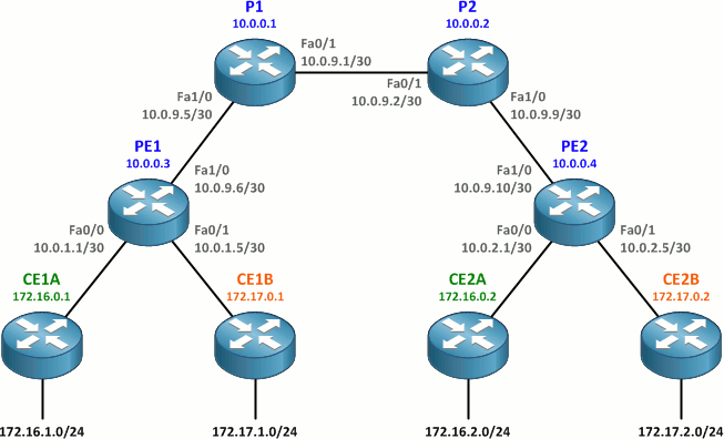
As a review, recall that
- P (provider) routers are ISP core routers which don't connect to customer routers and typically run only MPLS
- PE (provider edge) routers connect to customer sites and form the edge of a VPN
- CE (customer edge) routers exist at the edge of a customer site; they have no VPN awareness
- an IGP running among all P and PE routers is used to support LDP and BGP adjacencies within the provider network
- MP-BGP is run only among PE routers
- an IGP (typically) is run between each CE router and its upstream PE router
In our lab, OSPF is already in operation as the provider network IGP. OSPF processes have also been preconfigured on the CE routers; however, these OSPF topologies will remain separate from the provider OSPF.
There are five core tasks we need to accomplish to get an MPLS VPN up and running:
- Enable MPLS on the provider backbone.
- Create VRFs and assign routed interfaces to them.
- Configure MP-BGP between the PE routers.
- Configure OSPF between each PE router and its attached CE routers.
- Enable route redistribution between the customer sites and the backbone.
Although plenty of CLI outputs are shown below, you may want to grab the finished router configurations if you'd like to duplicate the lab on your own.
Enable MPLS
First we need to enable MPLS on all P-P and P-PE links with the mpls ip interface command. MPLS is not enabled on any CE-facing interfaces; CE routers do not run MPLS, just plain IP routing. LDP is enabled automatically as the default label distribution protocol (versus Cisco's legacy TDP). LDP typically runs between loopback addresses not directly reachable by LDP peers, which is why it's important to configure an IGP in the core before enabling MPLS.
We can verify the configuration of MPLS interfaces with show mpls interfaces.
P1(config)# interface f0/1
P1(config-if)# mpls ip
P1(config-if)# interface f1/0
P1(config-if)# mpls ip
P1(config-if)# do show mpls interfaces
Interface              IP            Tunnel   Operational
FastEthernet0/1        Yes (ldp)     No       Yes
FastEthernet1/0        Yes (ldp)     No       Yes
P2(config)# interface f0/1
P2(config-if)# mpls ip
P2(config-if)# interface f1/0
P2(config-if)# mpls ip
PE1(config)# interface f1/0
PE1(config-if)# mpls ip
PE2(config)# interface f1/0
PE2(config-if)# mpls ip
LDP adjacencies can be verified with the command show mpls ldp neighbor:
P1# show mpls ldp neighbor
    Peer LDP Ident: 10.0.0.2:0; Local LDP Ident 10.0.0.1:0
    TCP connection: 10.0.0.2.45114 - 10.0.0.1.646
    State: Oper; Msgs sent/rcvd: 12/13; Downstream
    Up time: 00:02:43
    LDP discovery sources:
      FastEthernet0/1, Src IP addr: 10.0.9.2
        Addresses bound to peer LDP Ident:
          10.0.9.2        10.0.9.9        10.0.0.2
    Peer LDP Ident: 10.0.0.3:0; Local LDP Ident 10.0.0.1:0
    TCP connection: 10.0.0.3.20327 - 10.0.0.1.646
    State: Oper; Msgs sent/rcvd: 12/12; Downstream
    Up time: 00:02:25
    LDP discovery sources:
      FastEthernet1/0, Src IP addr: 10.0.9.6
        Addresses bound to peer LDP Ident:
          10.0.9.6        10.0.0.3
Create and Assign VRFs
Our next step is to create customer VRFs on our PE routers and assign the customer-facing interfaces to them. We need to assign each VRF a route distinguisher (RD) to uniquely identify prefixes as belonging to that VRF and one or more route targets (RTs) to specify how routes should be imported to and exported from the VRF.
We'll use a route distinguisher for each VRF in the form of <ASN>:<customer number>. For simplicity, we'll reuse the same value as both an import and export route target within each VRF (though we are free to choose a different or additional route targets if we prefer). VRF configuration must be performed on both PE routers.
PE1(config)# ip vrf Customer_A
PE1(config-vrf)# rd 65000:1
PE1(config-vrf)# route-target both 65000:1
PE1(config-vrf)# ip vrf Customer_B
PE1(config-vrf)# rd 65000:2
PE1(config-vrf)# route-target both 65000:2
PE2(config)# ip vrf Customer_A
PE2(config-vrf)# rd 65000:1
PE2(config-vrf)# route-target both 65000:1
PE2(config-vrf)# ip vrf Customer_B
PE2(config-vrf)# rd 65000:2
PE2(config-vrf)# route-target both 65000:2
The command route-target both is used as a shortcut for the two commands route-target import and route-target export, which appear separately in the running configuration.
Now we need to assign the appropriate interfaces to each VRF and reapply their IP addresses. (Assigning an interface to a VRF automatically wipes it of any configured IP addresses. Your version of IOS may or may not inform you of this when it happens.) The command show ip vrf interfaces can be used to verify interface VRF assignment and addressing.
PE1(config)# interface f0/0
PE1(config-if)# ip vrf forwarding Customer_A
% Interface FastEthernet0/0 IP address 10.0.1.1 removed due to enabling VRF Customer_A
PE1(config-if)# ip address 10.0.1.1 255.255.255.252
PE1(config-if)# interface f0/1
PE1(config-if)# ip vrf forwarding Customer_B
% Interface FastEthernet0/1 IP address 10.0.1.5 removed due to enabling VRF Customer_B
PE1(config-if)# ip address 10.0.1.5 255.255.255.252
PE1(config-if)# ^Z
PE1# show ip vrf interfaces
Interface              IP-Address      VRF                              Protocol
Fa0/0                  10.0.1.1        Customer_A                       up
Fa0/1                  10.0.1.5        Customer_B                       up
PE2(config)# interface f0/0
PE2(config-if)# ip vrf forwarding Customer_A
% Interface FastEthernet0/0 IP address 10.0.2.1 removed due to enabling VRF Customer_A
PE2(config-if)# ip address 10.0.2.1 255.255.255.252
PE2(config-if)# interface f0/1
PE2(config-if)# ip vrf forwarding Customer_B
% Interface FastEthernet0/1 IP address 10.0.2.5 removed due to enabling VRF Customer_B
PE2(config-if)# ip address 10.0.2.5 255.255.255.252
PE2(config-if)# ^Z
PE2# show ip vrf interfaces
Interface              IP-Address      VRF                              Protocol
Fa0/0                  10.0.2.1        Customer_A                       up
Fa0/1                  10.0.2.5        Customer_B                       up
Configure MP-BGP on the PE Routers
This is where things start to get interesting. In order to advertise VRF routes from one PE router to the other, we must configure multiprotocol BGP (MP-BGP). MP-BGP is a little different from legacy BGP in that it supports multiple address families (e.g. IPv4 and IPv6) over a common BGP adjacency. It also supports the advertisement of VPN routes, which are longer than normal routes due to the addition of a 64-bit route distinguisher (which we assigned under VRF configuration).
MP-BGP runs only on the PE routers: P routers rely entirely on the provider IGP and MPLS to forward traffic through the provider network, and CE routers have no knowledge of routes outside their own VRF.
Minimal MP-BGP configuration is pretty straightforward. Both PE routers exist in BGP AS 65000.
PE1(config)# router bgp 65000
PE1(config-router)# neighbor 10.0.0.4 remote-as 65000
PE1(config-router)# neighbor 10.0.0.4 update-source loopback 0
PE1(config-router)# address-family vpnv4
PE1(config-router-af)# neighbor 10.0.0.4 activate
PE2(config)# router bgp 65000
PE2(config-router)# neighbor 10.0.0.3 remote-as 65000
PE2(config-router)# neighbor 10.0.0.3 update-source loopback 0
PE2(config-router)# address-family vpnv4
PE2(config-router-af)# neighbor 10.0.0.3 activate
If we look at the running configuration of the BGP process on either PE router, we notice that a bit more configuration than we provided has appeared:
PE1# show running-config | section router bgp
router bgp 65000
 no synchronization
 bgp log-neighbor-changes
 neighbor 10.0.0.4 remote-as 65000
 neighbor 10.0.0.4 update-source Loopback0
 no auto-summary
 !
 address-family vpnv4
  neighbor 10.0.0.4 activate
  neighbor 10.0.0.4 send-community extended
 exit-address-family
 !
 address-family ipv4 vrf Customer_B
  no synchronization
 exit-address-family
 !
 address-family ipv4 vrf Customer_A
  no synchronization
 exit-address-family
In addition to our VPNv4 address family, address families for the two customer VRFs have been created automatically. Also, support for extended community strings has been added to the VPNv4 neighbor configuration.
Verify that the MP-BGP adjacency between PE1 and PE2 was formed successfully with the command show bgp vpnv4 unicast all summary:
PE1# show bgp vpnv4 unicast all summary
BGP router identifier 10.0.0.3, local AS number 65000
BGP table version is 1, main routing table version 1

Neighbor        V    AS MsgRcvd MsgSent   TblVer  InQ OutQ Up/Down  State/PfxRcd
10.0.0.4        4 65000      12      12        1    0    0 00:06:05        0
Currently, there are no routes in the BGP table, because we have not specified anything to be advertised or redistributed, but we'll get to that after this next step.
Configure PE-CE OSPF
We just configured MP-BGP between the two PE routers. Now, let's configure an IGP between each PE router and its attached CE routers to exchange routes with the customer sites. We're going to use OSPF for this lab, but we could just as easily use another IGP like EIGRP or RIP.
Single-area OSPF has already been configured on the CE routers; all CE interfaces are in area 0. Remember that although we're using OSPF between each of the CE routers and its upstream PE router, these OSPF processes are isolated from the provider OSPF topology. The overall routing topology will look like this:
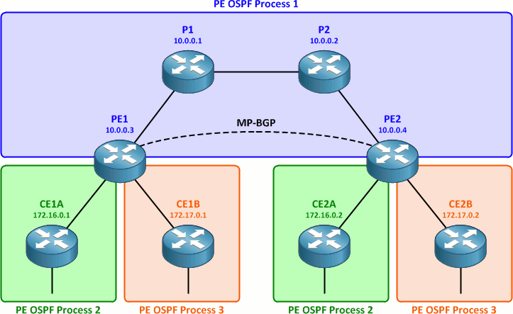
The provider OSPF process has already been configured on the PE routers as process 1. We'll configure an additional OSPF process for each CE router on each PE router. Each PE router will then have three OSPF processes total: one for the provider network, and one for each CE router. Whereas the provider OSPF process exists in the global routing table, the two CE processes will each be assigned to their respective customer VRFs.
PE1(config)# router ospf 2 vrf Customer_A
PE1(config-router)# router-id 10.0.1.1
PE1(config-router)# interface f0/0
PE1(config-if)# ip ospf 2 area 0
PE1(config-if)# router ospf 3 vrf Customer_B
PE1(config-router)# router-id 10.0.1.5
PE1(config-router)# interface f0/1
PE1(config-if)# ip ospf 3 area 0
PE2(config)# router ospf 2 vrf Customer_A
PE2(config-router)# router-id 10.0.2.1
PE2(config-router)# interface f0/0
PE2(config-if)# ip ospf 2 area 0
PE2(config-if)# router ospf 3 vrf Customer_B
PE2(config-router)# router-id 10.0.2.5
PE2(config-router)# interface f0/1
PE2(config-if)# ip ospf 3 area 0
We should see each PE router form an OSPF adjacency with both of its attached CE routers, and the customer routes should appear in the VRF tables on the PE routers.
PE1# show ip route vrf Customer_A

Routing Table: Customer_A
...

172.16.0.0/16 is variably subnetted, 2 subnets, 2 masks
O       172.16.1.0/24 [110/11] via 10.0.1.2, 00:04:21, FastEthernet0/0
O       172.16.0.1/32 [110/11] via 10.0.1.2, 00:04:21, FastEthernet0/0
     10.0.0.0/30 is subnetted, 1 subnets
C       10.0.1.0 is directly connected, FastEthernet0/0
PE1# show ip route vrf Customer_B

Routing Table: Customer_B
...

172.17.0.0/16 is variably subnetted, 2 subnets, 2 masks
O       172.17.1.0/24 [110/11] via 10.0.1.6, 00:03:03, FastEthernet0/1
O       172.17.0.1/32 [110/11] via 10.0.1.6, 00:03:04, FastEthernet0/1
     10.0.0.0/30 is subnetted, 1 subnets
C       10.0.1.4 is directly connected, FastEthernet0/1
Configure Route Redistribution
We're almost done! We have our MPLS and MP-BGP backbone up and running, and our CE routers are sending routes to our PE routers within their VRFs. The last step is to glue everything together by turning on route redistribution from the customer-side OSPF processes into MP-BGP and vice versa on the PE routers.
First we'll configure redistribution of CE routes in each VRF into MP-BGP. This is done under the BGP IPv4 address family for each VRF.
PE1(config)# router bgp 65000
PE1(config-router)# address-family ipv4 vrf Customer_A
PE1(config-router-af)# redistribute ospf 2
PE1(config-router-af)# address-family ipv4 vrf Customer_B
PE1(config-router-af)# redistribute ospf 3
PE2(config)# router bgp 65000
PE2(config-router)# address-family ipv4 vrf Customer_A
PE2(config-router-af)# redistribute ospf 2
PE2(config-router-af)# address-family ipv4 vrf Customer_B
PE2(config-router-af)# redistribute ospf 3
This enables redistribution of OSPF routes into BGP for transport across the provider network between the two sites. We can verify that the routes learned from the customer sites (the 172.16.0.0/16 and 172.17.0.0/16 networks) now appear in the BGP tables for their respective VRFs.
PE1# show ip bgp vpnv4 vrf Customer_A
...

Network          Next Hop            Metric LocPrf Weight Path
Route Distinguisher: 65000:1 (default for vrf Customer_A)
*> 10.0.1.0/30      0.0.0.0                  0         32768 ?
*>i10.0.2.0/30      10.0.0.4                 0    100      0 ?
*> 172.16.0.1/32    10.0.1.2                11         32768 ?
*>i172.16.0.2/32    10.0.0.4                11    100      0 ?
*> 172.16.1.0/24    10.0.1.2                11         32768 ?
*>i172.16.2.0/24    10.0.0.4                11    100      0 ?
PE1# show ip bgp vpnv4 vrf Customer_B
...

Network          Next Hop            Metric LocPrf Weight Path
Route Distinguisher: 65000:2 (default for vrf Customer_B)
*> 10.0.1.4/30      0.0.0.0                  0         32768 ?
*>i10.0.2.4/30      10.0.0.4                 0    100      0 ?
*> 172.17.0.1/32    10.0.1.6                11         32768 ?
*>i172.17.0.2/32    10.0.0.4                11    100      0 ?
*> 172.17.1.0/24    10.0.1.6                11         32768 ?
*>i172.17.2.0/24    10.0.0.4                11    100      0 ?
The last step is to complete the redistribution in the opposite direction: from BGP into the customer OSPF processes. If you're accustomed to route redistribution, there's nothing new here. (We don't have to specify any VRF information in the redistribution statement because each customer OSPF process is already assigned to a VRF.)
PE1(config)# router ospf 2
PE1(config-router)# redistribute bgp 65000 subnets
PE1(config-router)# router ospf 3
PE1(config-router)# redistribute bgp 65000 subnets
PE2(config)# router ospf 2
PE2(config-router)# redistribute bgp 65000 subnets
PE2(config-router)# router ospf 3
PE2(config-router)# redistribute bgp 65000 subnets
Testing and Confirmation
If has gone well, we should now have end-to-end connectivity between the CE routers within each VRF. Both routers for each customer should now have complete routing tables. Here are customer A's routes:
CE1A# show ip route
...

172.16.0.0/16 is variably subnetted, 4 subnets, 2 masks
C       172.16.1.0/24 is directly connected, Loopback1
C       172.16.0.1/32 is directly connected, Loopback0
O IA    172.16.2.0/24 [110/21] via 10.0.1.1, 00:03:50, FastEthernet0/0
O IA    172.16.0.2/32 [110/21] via 10.0.1.1, 00:03:50, FastEthernet0/0
     10.0.0.0/30 is subnetted, 2 subnets
O IA    10.0.2.0 [110/11] via 10.0.1.1, 00:03:50, FastEthernet0/0
C       10.0.1.0 is directly connected, FastEthernet0/0
CE2A# show ip route
...

172.16.0.0/16 is variably subnetted, 4 subnets, 2 masks
O IA    172.16.1.0/24 [110/21] via 10.0.2.1, 00:02:49, FastEthernet0/0
O IA    172.16.0.1/32 [110/21] via 10.0.2.1, 00:02:49, FastEthernet0/0
C       172.16.2.0/24 is directly connected, Loopback1
C       172.16.0.2/32 is directly connected, Loopback0
     10.0.0.0/30 is subnetted, 2 subnets
C       10.0.2.0 is directly connected, FastEthernet0/0
O IA    10.0.1.0 [110/11] via 10.0.2.1, 00:02:49, FastEthernet0/0
You may notice that OSPF routes sent between two sites belonging to the same customer appear as inter-area routes. Remember that although OSPF area 0 is being used at both sites, each site exists as a separate link-state topology connected by the MPLS VPN.
We should be able to ping from one CE router to the other. (Remember that we don't need to specify a VRF when doing so because CE routers have no knowledge that they're in a VRF.)
CE1A# ping 172.16.0.2

Type escape sequence to abort.
Sending 5, 100-byte ICMP Echos to 172.16.0.2, timeout is 2 seconds:
!!!!!
Success rate is 100 percent (5/5), round-trip min/avg/max = 12/21/32 ms
We can perform a traceroute to verify the path taken as well as the MPLS labels used to traverse the provider network.
CE1A# traceroute 172.16.0.2

Type escape sequence to abort.
Tracing the route to 172.16.0.2

1 10.0.1.1 4 msec 4 msec 8 msec
  2 10.0.9.5 [MPLS: Labels 19/22 Exp 0] 16 msec 12 msec 24 msec
  3 10.0.9.2 [MPLS: Labels 19/22 Exp 0] 24 msec 20 msec 16 msec
  4 10.0.2.1 [MPLS: Label 22 Exp 0] 20 msec 16 msec 24 msec
  5 10.0.2.2 16 msec *  36 msec
Here's a packet capture of the above traceroute if you're interested in how the MPLS label information is returned. And again, here are the the finished router configurations if you'd like to replicate the lab yourself.
(Thanks to Ivan Pepelnjak of Cisco IOS Hints helping revise this article!)
Comments
May 16, 2011 at 3:59 a.m. UTC
Thanks...
May 16, 2011 at 6:14 a.m. UTC
Hi Jeremy,
Good post. I'm having some problems with this sentence:
"We need to assign each VRF a route distinguisher (RD) to uniquely identify prefixes as belonging to that VRF and one or more route targets (RTs) to specify how routes should be imported to and exported from the VRF."
This could be due to english not being my native language but this sounds like you're saying that RD defines the VPN and this is not true. The RD only makes prefixes unique but does not in any way define the VPN, that's what the RT is for.
I'm surprised Ivan didn't catch this if he read the article. Could just be a
misunderstanding from my part or you should rewrite that sentence.
May 16, 2011 at 7:31 a.m. UTC
An excellent post. Thanks Jeremy.
May 16, 2011 at 8:53 a.m. UTC
Stretch, As always there is only one word to describe this post: excellent !
Regards, Alain
May 16, 2011 at 1:12 p.m. UTC
If you ever plan to implement IPv6, its much easier to add if you use "vrf definition " instead of "ip vrf "
vrf definition vrf2
 rd 2:2
 !
 address-family ipv4
 route-target export 2:2
 route-target import 2:2
 exit-address-family
-
Trey
May 16, 2011 at 2:09 p.m. UTC
thanks
May 16, 2011 at 3:12 p.m. UTC
@Daniel:
It must be a language barrier thing. It simply means that the RD is used to make routes unique (e.g. when customers use overlapping address space).
May 16, 2011 at 5:20 p.m. UTC
Many thanks !!
May 16, 2011 at 6:30 p.m. UTC
Yes, RD does nothing more than make the routes unique so that BGP will distribute them correctly.
People often get confused about the RD because nearly all cisco examples I have seen use the same RD on both PE routers, giving people the false impression that this is required.
You can just as easily use one RD per VRF per PE. Thats what I usually do in examples just to remind people that RT and RD are two different things.
May 17, 2011 at 11:39 a.m. UTC
Thanks Jeremy,My hero
May 17, 2011 at 6:23 p.m. UTC
...and sometimes you want to use only MP-BGP and do not carry any prefixes and then you add "no bgp default ipv4-unicast" under the "router bgp 65001"-context.
Thanx for this short and concise post.
May 17, 2011 at 8:15 p.m. UTC
Thanks Stretch! It helped me a lot for MPLS config understanding!
May 17, 2011 at 9:38 p.m. UTC
Hi, i read your your posts almoust two years and i must say THANK YOU. You are the best.
regards,
Alen
May 18, 2011 at 7:26 a.m. UTC
Using OSPF on PE-CE is limited by a number of OSPF processes on PE router. There are only 32. That means you can not connect more than 30 unique CE to one PE (http://www.cisco.com/en/US/tech/tk365/technologies_q_and_a_item09186a0080094704.shtml#q46)
Thats why OSPF isn't the best choise for
IS-IS is not supported there at all.
May 19, 2011 at 3:37 a.m. UTC
THANK YOU for the post man. Hope you will discuss L2 VPN (Martini & Kompella) soon....we are waiting :)
May 19, 2011 at 4:49 p.m. UTC
Good introduction i will add two remarks :
- check ip cef before enabling mpls because mpls needs it
- create dedicated loopbacks and force the mpls router-id to them
Those avoid you from potential problems you will see after more practices :)
May 22, 2011 at 2:54 p.m. UTC
thank you so much Jeremy.. It is an excellent introductory config to understand basics of mpls. You are great..!
June 20, 2011 at 7:07 p.m. UTC
Thanks Jeremy. This example has really helped me understand the concept even further. Writing BGP+MPLS in 3 weeks. Wish me well!
October 6, 2011 at 6:07 a.m. UTC
Your network topology looks great. Thank you for sharing this.
November 4, 2011 at 2:35 p.m. UTC
great post Jeremy,
but my doubt is how can I improve the using MPLS VPNs,
I am Brazilian and my CBT is on this issue, and I'm still "raw"
regarding the issue, I would like your help.
January 13, 2012 at 6:48 p.m. UTC
dear Jeremy Stretch Thanks for your awesome scenario. but 1 thing is missing, i was working on this topology for 4 to 5 hours but my VRF sites was not able to communicate with each other and you said on this scenario that
neighbor 10.0.0.4 send-community extended
will generate automatically, but i didn't, then i contacted with my friend he told that put that command manually then it worked.
January 24, 2012 at 8:04 p.m. UTC
Simply supub!!! Thanks for your post...
March 3, 2012 at 3:47 a.m. UTC
hi waleed143,this may be a issue in regards to the ios version,but is must be configured.Another question about this command is my practice lab book stated that it must be configured to send-community both.What's the difference?
April 19, 2012 at 5:15 p.m. UTC
you are awesome jeremy!!!!!! thanks for bein a lifesaver
May 5, 2012 at 9:11 p.m. UTC
Hi Jeremy,
Thanks for the post. It is a great use for MPLS beginners like me.
One small query. You had mentioned that an IGP needs to run at core( that is, between PE routers and P routers - OSPF mostly).This is needed for PE routers to believe that IGP connectivity is available and they can proceed with exchanging the prefixes.
But in configuration you have not configured that. I do understand that it is responsiblity of the service providers in real life to configure the IGPs at the core.
However, for the above example configuration, can you please confirm that we must configure the IGP (preferrably OSPF) at the core in case for the above configuration to work.
Please guide. Thanks again for your wonderful piece of work.
September 5, 2012 at 6:38 a.m. UTC
Hi, Jeremy
this is the second time I read your article and all of your instruction work really well!!
Big thanks to you Jeremy.
for PE - P router, you must enable the IGP (in your case and my case is OSPF) to be able to advertise the LDP though all the P and PE router by executing some commands.
router ospf 8
 mpls ldp sync
 mpls ldp autoconfig area 0
 router-id 10.28.1.111
 log-adjacency-changes
 area 0 authentication
 network 10.0.0.0 0.255.255.255 area 0
October 19, 2012 at 7:24 p.m. UTC
Hey man, thanks for this great tutorial, been banging my head to really find out what exactly goes on in the "cloud"
November 18, 2012 at 3:07 p.m. UTC
Excellent tutorial!!!
December 4, 2012 at 7:52 a.m. UTC
Hi Stretch,
Thank you for the forum with so much informational material and these helpful articles.
I was trying to practice the same concept with some other topology and had faced one issue which i am facing with this one as well.
Now I configured this lab as you explained in detailed but still the same issue that is, i am getting routes from the other site but i am not able to ping that network / other site.
I verified the config so many times. Routing tables and config all are as you mentioned even then i am not able to reach the other site.
What can be the possible reason
Regards/Imran
December 13, 2012 at 2:03 p.m. UTC
Shouldn't the final traceroute be performed from PE1 and not CE1A, CE1A won't see the MPLS lables.
January 25, 2013 at 9:56 p.m. UTC
excellent post stretch, just purely excellent
February 1, 2013 at 12:04 p.m. UTC
Hi,
This is really a nice lab.
Helped me pretty much in learning PE-CE topology.
Thanks
February 23, 2013 at 11:48 p.m. UTC
Could you please explain why the traceroute output show the following output.
4 10.0.2.1 [MPLS: Label 22 Exp 0] 20 msec 16 msec 24 msec
Why we can't see the following output instead the one above?
4 10.0.9.10 [MPLS: Label ? Exp 0] 20 msec 16 msec 24 msec
March 11, 2013 at 1:42 p.m. UTC
Can you please do a show mpls information-table so we can see the action for that the LSR is going to take when it forwards the packet down the LSP?
Thanks.
March 21, 2013 at 7:35 p.m. UTC
you broke it down in its simplest terms. Thank you Jeremy
Heresy
April 19, 2013 at 6:25 a.m. UTC
God. Just God=)
April 26, 2013 at 8:48 a.m. UTC
very nice
April 30, 2013 at 2:23 p.m. UTC
ive gone through this lab which is wikid.
But im having issues CE1A cant ping 172.16.0.2 like in the tutorial. Im seeing all the routes when i do a show ip bgp vpnv4 vrf Customer_A & for B but still nothing. Im very new on MPLS and I would like to take it to the next level. Any help would be amazing.
Thanks
April 30, 2013 at 6:01 p.m. UTC
Thank you very much.
It struggles me while looking to the Cisco manual
July 25, 2013 at 11:56 p.m. UTC
thanks mate..very useful!!
August 10, 2013 at 10:07 p.m. UTC
Bob i have an answer to you and to anyone who can't replicate this topology with successful ping between sites.
%BGP-4-VPNV4NH_MASK : Nexthop [IP_address] may not be reachable from neigbor [IP_address] - not /32 mask
ExplanationA VPNv4 route is being sent to the IBGP neighbor. The address of the next hop is a loopback interface that does not have a /32 mask defined. OSPF is being used on this loopback interface, and the OSPF network type of this interface is LOOPBACK. OSPF advertises this IP address as a host route (with mask /32), regardless of what mask is configured. This advertising conflicts with TDP, which uses configured masks, so the TDP neighbors may not receive a tag for the route indicated in this error message. This condition could break connectivity between sites that belong to the same VPN.
Recommended ActionConfigure the loopback that is being used as the next-hop loopback to use a 32-bit network mask (/32), or set the network type to point-to-point by entering the ip ospf network point-to-point command.
The explanation is quite simple: OSPF announced the loopback IP addresses as host routes (/32). LDP was expecting to find a /24 address at the routing table. Since it couldn’t find it, it didn’t advertise a label for this FEC!!
October 31, 2013 at 3:58 p.m. UTC
how can i use these config files in gns3?
December 27, 2013 at 9:51 a.m. UTC
Nice post, thanks! Like a brief instructions for ISPs :)
December 31, 2013 at 2:06 p.m. UTC
Can't thank you that much that you deserve.
Top one, Jeremy...
January 1, 2014 at 9:14 p.m. UTC
Thanks!!!
January 6, 2014 at 8:45 p.m. UTC
Thanks ;)
February 14, 2014 at 2:37 p.m. UTC
Tnx man, it helped me a lot!!!!
Cheers!
March 27, 2014 at 2:00 p.m. UTC
Thanks for a great write up on MPLS VPN. I read your VRF and MPLS guides first and they too are very well written and easy to understand.
Thanks again,
Mitchell
March 31, 2014 at 11:44 p.m. UTC
thank you
July 6, 2014 at 9:23 p.m. UTC
what if i have four PE roters then hows my configuration will be effected compare to this one...?
August 11, 2014 at 5:22 p.m. UTC
Hi there, need help. I have created the MPLS topology with EIGRP ...it's all working. Your article is great and I did all configs till ""show bgp vpnv4 unicast all summary" and all working great. However I don't know but OSPF is just not working and hence I need to connect CE using EIGRP..Can you please with configuration required at CE and PE with EIGRP...I did visit ciso links for EIGRP configs on PE and CE but I am doing something wrong.....can you please help!!
September 11, 2014 at 10:34 a.m. UTC
How we create l3 mpls vpn for customers having more than two sites ? Do we need to create separate point to point paths by defining a new vrf at PE router ?
September 23, 2014 at 8:53 p.m. UTC
Great explaination! Make so difficult thing so easier to understand
November 11, 2014 at 5:34 p.m. UTC
Great Thank you
January 15, 2015 at 6:00 p.m. UTC
Hi, very nice ordered explanation - great work! One proposition. In the end of the article you are pointing on the inter-area type of the OSPF routes. Probably that's the best place to make some reference to the OSPF sham-link... Greets!
January 23, 2015 at 8:12 p.m. UTC
excellent
January 28, 2015 at 10:24 a.m. UTC
Is it possible to use real interface instead of using loop back interface in MP-BGP confiuration?
February 2, 2015 at 2:43 p.m. UTC
A nice post...
February 13, 2015 at 12:39 p.m. UTC
Very nice post, i did learn a lot with this lab on gns3.
June 10, 2015 at 8:36 a.m. UTC
i am having a little challenge with MPLS route redistribution. though i have a little bit more hard settings from CBTnuggets mpls fundamental settings. one of my CP is well converge but the second CP siteA-SiteB did not at all. am a bit confused identifying what i did wrong. am labbing with GNS3 c7200 ISO used.
July 7, 2015 at 4:44 p.m. UTC
You can use Web IOU instead of GNS3. I implemented this lab and it works pretty well.
August 5, 2015 at 3:30 p.m. UTC
Thank you so much. this post very helpful to me to understand the MPLS clearly.
Thank you Jeremy
August 12, 2015 at 12:46 p.m. UTC
Thanks for the post. Excellent. But I have one question. How can you use one PE port to serve multiple customers.
September 23, 2015 at 5:21 p.m. UTC
Thanks for the Interesting & Informative post. I have a Question. In the above Scenario - All PE routers are Running OSPF as IGP to exchange PE's Reach-ability information with in same AS. What if Routers are across different AS and manged by different Providers? How is the MPLS VPN Deployment across Customer-sites connected by different Providers? Do you have information about real time deployments?
October 2, 2015 at 10:20 a.m. UTC
Hi Jeremy,
I hope you can create a section for MPLS VPN using BGP on PE and CE sites since in large enterprises, that is how the customers now usually want their MPLS implementation to have more granular control on their advertisements.
December 24, 2015 at 11:47 a.m. UTC
Great article! Thank you so much!
March 17, 2016 at 5:22 a.m. UTC
Amazing article. You made my day :) Thank you
March 20, 2016 at 10:16 p.m. UTC
Is it possible to have a multi-site BGP MPLS VPN? I've never seen any examples with more than 2 Provider Edge routers. Is this possible?
March 24, 2016 at 2:08 a.m. UTC
Thanks Jeremy!! I always enjoy your articles.
One thing I am not quite sure is the output of routing tables on CE1A and CE2A. I thought there should be some external type routes in it due to BGP-OSPF redistribution but "O IA" type routes over there instead. Am I missing some big piece of MPLS puzzle here?
Someone can explain it for me?
Thanks, Paul
April 2, 2016 at 3:21 a.m. UTC
Thank you. Nailed it. Finally got it.
April 11, 2016 at 4:54 a.m. UTC
What configurations were done to get OSPF working and the routing tables right?
April 14, 2016 at 10:58 p.m. UTC
Hi, thanks for your help. Can mpls vpn be set without making use of vrf?
April 18, 2016 at 3:48 p.m. UTC
Hello Jeremy,
nice post as usual. jst a config oversight but for pe1 and pe2's redistribution of bgp routes into the vrf running ospf it should read 'router ospf 2 vrf Customer_A' and 'router ospf 3 vrf Customer_B' instead of just router ospf 2 and router ospf 3
April 23, 2016 at 2:23 p.m. UTC
How does this works if Customer A and Customer B has the same ip pools to be advertised?
April 27, 2016 at 5:13 p.m. UTC
great article
May 5, 2016 at 7:15 a.m. UTC
Nice descriptive post. I tried to configure by myself in GNS3 lab. All the intermediate results were same as in post. Still I couldn't ping from Customer_A2 to Customer_A2. Then I downloaded configs from this page. And that worked. I tried to find difference between mine configs and their config. I couldn't find any significant difference.
June 15, 2016 at 5:37 p.m. UTC
I like the simplicity of the explanation. Thanks. It was very helpful.
June 15, 2016 at 5:46 p.m. UTC
What will be the output of 'sh ip route' at PE1 &2. Will the VRFs be distinguished by the RD values in the forwarding table?
June 16, 2016 at 5:31 a.m. UTC
Thanks Jeremy, it was very helpful.
July 21, 2016 at 6:41 p.m. UTC
I am trying to run this config on CISCO 2600 series router, I have an issue. What should be the IP address for the CE routers, should be in the same sub net as the PE routers or random considering that we are creating asn ISP scenario
September 23, 2016 at 7:52 a.m. UTC
Jeremy, I am always a fan of your articles and the way you explain the technology. Thanks. I've one question you could possibly help me finding an answer. I've been searching all over the internet about the examples of vrf-lite with BGP as the the routing protocol and I could not find even one example. I am not sure if this is even configurable or the BGP can only be configured in the normal VRF (VRF with MPLS and not VRF-lite)? I would really appreciate if you could give some examples. Thanks.
September 29, 2016 at 4:16 p.m. UTC
i have a question that is no concern to this lab :), what is the tool that you used for the MPLS/OSPF diagram?
PD: I am a follower of your blog now.
October 12, 2016 at 5:23 p.m. UTC
Thanks, Jeremy. Great, clean and informative post as always. Just few notes regarding some issues/questions mentioned in comments above:
1) Ability to see MPLS label in traceroute. This depends on the CE router model/IOS you use in GNS3 lab (or as a physical equipment. C3725 with AdvEnterprise IOS works just fine and shows all the labels. However when I tried to use 36xx with IOS, which does not "understand" what MPLS is, it just displayed regular trace route. So check IOS on your CE if you do not see MPLS labels in traceroute. You do not have to enable MPLS on CE, of course, but it must be able to interpret ICMP messages with label info received in order to display them. Traceroute from PE will, naturally, show label info as it does support MPLS.
2) OSPF interarea routes in CE routing table. Interestingly, when doing my own lab I received E2 (external routes at first), which was not unexpected because we use redistribution between routing protocols (OSPF->BGP->OSPF). However as we use extended communities in MP-BGP info about the originating routing protocol (including process number) is preserved, delivered to the remote BGP peer and is used during BGP->OSPF redistribution. So if OSPF process numbers are the same as in this Jeremy's lab, resulting route will be shown as interarea (IA) and not as External (E2). As it was mentioned earlier it will be IA even though Area 0 is used at both sides. And the only reason I received E2 instead of IA is that I initially used different OSPF process numbers at either side. Once I changed them to the same value< I got IA.
3) Limitations of IGP instances which you can run on PE to peer with Customer's CEs. That is correct, but that is the reason that (e)BGP is often used for this purpose. You can easily modify this lab and replace PE-CE OSPF process with redistribution to/from BGP into CE-PE eBGP peering. All you need to do is to configure BGP process on CE router, peer it (under address-family ipv4 vrf Customer_X section) with PE connected interface IP (not loopback!) and configure networks list to be advertised from CE to PE. No extra processes, mo mess with the redistribution. Just remember, that BGP AS numbers at each Customer site must be unique and differ from the provider's ASN. For example if AS65000 is used by the provider (as in the Lab), you can use AS65101 for CE1A and AS56102 for CE2A. Just keep in mind that you will probably need to use CE loopback interface for ping/traceroute as outbound CE-PE link IP subnet will likely not be included in BGP advertisement.
4) Use of overlapping networks by CustomerA and CustomerB. Any networks inside each Customer routing domain can overlap with other customers. VRF-BGP-MPLS will take care of it. The only unique networks (most likely) required are CE-PE links as they are part of provider iBGP process and are likely to be configured on the same PE router anyways.
5) IGP inside Provider cloud in order for MPLS and iBGP to work. Can be any IGP, can even be static (in lab, not in real life :-))
Hope this helps.
Thanks again for the good article and really helpful MPLS lab!
October 18, 2016 at 1:50 a.m. UTC
Thanks. Great article.