The premiere source of truth powering network automation. Open and extensible, trusted by thousands.
NetBox is now available as a managed cloud solution! Stop worrying about your tooling and get back to building networks.
Inter-VRF Routing with VRF Lite
By stretch | Monday, March 29, 2010 at 4:29 a.m. UTC
In Intro to VRF lite, we looked at how virtual routing and forwarding (VRF) instances can be employed to logically separate the layer three topologies of unrelated entities sharing a single physical infrastructure. VRFs work at layer three much like VLANs work at layer two, by assigning interfaces to a virtual domain isolated from other virtual domains at the same layer. This is a simple concept to grasp so long as each of the VRFs are maintained in isolation. However, things get a bit more complex when you need to route traffic from one VRF to another.
Consider the following topology, which might be found at a small business park or college campus.
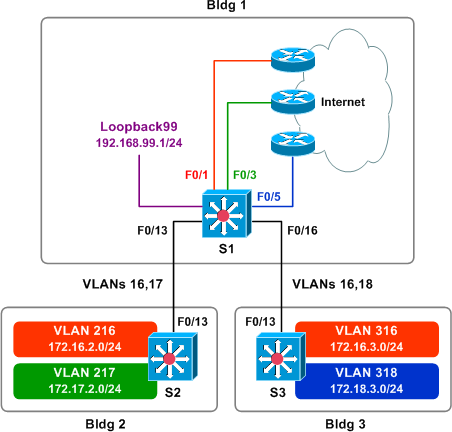
The network pictured serves three customers: we'll call them customers Red, Green, and Blue. Each customer has its own Internet connection, housed in building one. Customer Green has employees in building two, customer Blue has employees in building three, and customer Red has employees in both buildings two and three. Additionally, VOIP service and connection to the PSTN (represented for now by a loopback interface) will be provided in the future by the network operator to customers Red and Green, but not Blue.
Buildings two and three are connected to building one via 802.1Q trunk links. All three customers rely on the same physical network infrastructure for connectivity, but the traffic from each customer must be isolated from the others for security reasons. The IP prefixes in use are as follows:
- Red: 172.16.0.0/16
- Green: 172.17.0.0/16
- Blue: 172.18.0.0/16
- VOIP Services: 192.168.99.0/24
The design question posed by this scenario is as follows: how can we provide local VOIP connectivity to some customers while keeping all of the customers isolated from one another?
Modifying the Multilayer Switches' SDM Template
Before we can implement VRFs on our multilayer switches (Catalyst 3550s, in this case), we have to modify how the internal ternary content-addressable memory (TCAM) is partitioned to store IP routes. Observe what happens if we attempt to enable VRF with the default SDM template:
S1(config)# ip routing
S1(config)# ip vrf Red
S1(config-vrf)#
%L3TCAM-3-SIZE_CONFLICT: VRF requires enabling extended routing
VRF routes require that an additional unique identifier, a route distinguisher, is prepended to each VRF route in the routing table (we'll cover this in more detail shortly). To accommodate for this, the TCAM must be repartitioned. (This step is only necessary when configuring VRFs on certain multilayer switches.)
S1(config)# sdm prefer extended-match
Changes to the running SDM preferences have been stored, but cannot take effect
until the next reload.
Use 'show sdm prefer' to see what SDM preference is currently active.
S1(config)# ^Z
S1# show sdm prefer
 The current template is the default template.
 The selected template optimizes the resources in
 the switch to support this level of features for
 8 routed interfaces and 1K VLANs.

number of unicast mac addresses:   5K
 number of igmp groups:             1K
 number of qos aces:                1K
 number of security aces:           1K
 number of unicast routes:          8K
 number of multicast routes:        1K

The template stored for use after the next reload
 is the default extended-match template.
 The selected template optimizes the resources in
 the switch to support this level of features for
 8 routed interfaces and 1K VLANs.

number of unicast mac addresses:   5K
 number of igmp groups:             1K
 number of qos aces:                1K
 number of security aces:           1K
 number of unicast routes:          4K
 number of multicast routes:        1K
Note that the supported number of unicast routes has been halved from 8K to 4K.
We need to apply this change to and reload all three switches before proceeding.
Creating VRFs
We need to create four VRFs on S1: one for each of the three customers, and one for the shared VOIP network. Each VRF must be assigned a unique route distinguisher. A route distinguisher is simply a unique number stored beside each route in the routing table to associate it with its VRF and maintain uniqueness should two or more VRFs have overlapping address space (for example, if all three of our customers were addressed out of the 10.0.0.0/8 network).
There are two formats in which we can define a route distinguisher: <ASN>:<number> or <IP address>:<number>, where number is an arbitrary decimal number. Which method we choose is arbitrary. While the format of route distinguishers is an important design consideration in "real" VPNs, in VRF lite (i.e. VRFs without MPLS) it is only a locally-significant value. We'll use the <ASN>:<number> format with the private ASN 65000 (which will also be used for our BGP configuration later in the article) and number customers sequentially beginning from 1.
S1
ip routing
!
ip vrf Red
 rd 65000:1
!
ip vrf Green
 rd 65000:2
!
ip vrf Blue
 rd 65000:3
!
ip vrf Shared
 rd 65000:99
Next, we assign the physical and logical interfaces to VRFs and address them appropriately. We're using a loopback interface in place of a physical interface on S1 to emulate the shared VOIP network, however there is no effective difference with regard to VRF configuration. Note that interfaces must be assigned to a VRF before being addressed; assigning an interface to a VRF wipes any IP addresses already configured on that interface.
S1
vlan 16
vlan 17
vlan 18
!
interface Loopback99
 description VOIP Services
 ip vrf forwarding Shared
 ip address 192.168.99.1 255.255.255.0
!
interface FastEthernet0/1
 no switchport
 ip vrf forwarding Red
 ip address 172.16.1.2 255.255.255.252
!
interface FastEthernet0/3
 no switchport
 ip vrf forwarding Green
 ip address 172.17.1.2 255.255.255.252
!
interface FastEthernet0/5
 no switchport
 ip vrf forwarding Blue
 ip address 172.18.1.2 255.255.255.252
!
interface FastEthernet0/13
 switchport trunk encapsulation dot1q
 switchport mode trunk
!
interface FastEthernet0/16
 switchport trunk encapsulation dot1q
 switchport mode trunk
!
interface Vlan16
 ip vrf forwarding Red
 ip address 172.16.0.1 255.255.255.0
!
interface Vlan17
 ip vrf forwarding Green
 ip address 172.17.0.1 255.255.255.0
!
interface Vlan18
 ip vrf forwarding Blue
 ip address 172.18.0.1 255.255.255.0
The physical trunk interfaces F0/13 and F0/16 are not assigned to a VRF, because they are not routed interfaces. VRF configuration is only relevant at layer three.
We can use show ip vrf to examine the VRFs and their assigned interfaces:
S1# show ip vrf
  Name                             Default RD          Interfaces
  Blue                             65000:3             Fa0/5
                                                       Vl18
  Green                            65000:2             Fa0/3
                                                       Vl17
  Red                              65000:1             Fa0/1
                                                       Vl16
  Shared                           65000:99            Lo99
S1# show ip vrf interfaces
Interface              IP-Address      VRF                              Protocol
Fa0/5                  172.18.1.2      Blue                             up
Vl18                   172.18.0.1      Blue                             up
Fa0/3                  172.17.1.2      Green                            up
Vl17                   172.17.0.1      Green                            up
Fa0/1                  172.16.1.2      Red                              up
Vl16                   172.16.0.1      Red                              up
Lo99                   192.168.99.1    Shared                           up
We only need to create two VRFs on each of the two other switches, as each connects only two customers, and assign the appropriate interfaces.
S2
ip routing
!
ip vrf Red
 rd 65000:1
!
ip vrf Green
 rd 65000:2
!
vlan 16
vlan 17
vlan 216
vlan 217
!
interface FastEthernet0/13
 switchport trunk encapsulation dot1q
 switchport mode trunk
!
interface Vlan16
 ip vrf forwarding Red
 ip address 172.16.0.2 255.255.255.0
!
interface Vlan17
 ip vrf forwarding Green
 ip address 172.17.0.2 255.255.255.0
!
interface Vlan216
 ip vrf forwarding Red
 ip address 172.16.2.1 255.255.255.0
!
interface Vlan217
 ip vrf forwarding Green
 ip address 172.17.2.1 255.255.255.0
S3
ip routing
!
ip vrf Red
 rd 65000:1
!
ip vrf Blue
 rd 65000:3
!
vlan 16
vlan 18
vlan 316
vlan 318
!
interface FastEthernet0/13
 switchport trunk encapsulation dot1q
 switchport mode trunk
!
interface Vlan16
 ip vrf forwarding Red
 ip address 172.16.0.3 255.255.255.0
!
interface Vlan18
 ip vrf forwarding Blue
 ip address 172.18.0.3 255.255.255.0
!
interface Vlan316
 ip vrf forwarding Red
 ip address 172.16.3.1 255.255.255.0
!
interface Vlan318
 ip vrf forwarding Blue
 ip address 172.18.3.1 255.255.255.0
Configuring OSPF
Next we'll configure OSPF to exchange routes among the three buildings. Three independent OSPF processes are to be run, one per customer VRF. OSPF configuration here is pretty straight forward, as we can simply place all interfaces in area 0 within each VRF.
S1
router ospf 1 vrf Red
 network 0.0.0.0 255.255.255.255 area 0
!
router ospf 2 vrf Green
 network 0.0.0.0 255.255.255.255 area 0
!
router ospf 3 vrf Blue
 network 0.0.0.0 255.255.255.255 area 0
S2
router ospf 1 vrf Red
 network 0.0.0.0 255.255.255.255 area 0
 passive-interface Vlan216
!
router ospf 2 vrf Green
 network 0.0.0.0 255.255.255.255 area 0
 passive-interface Vlan217
!
S3
router ospf 1 vrf Red
 network 0.0.0.0 255.255.255.255 area 0
 passive-interface Vlan316
!
router ospf 3 vrf Blue
 network 0.0.0.0 255.255.255.255 area 0
 passive-interface Vlan318
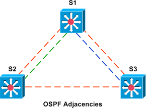
We can verify that OSPF adjacencies have been appropriately established with show ip ospf neighbor. Note that this command is not VRF-specific.
S1# show ip ospf neighbor

Neighbor ID     Pri   State           Dead Time   Address         Interface
172.18.3.1        1   FULL/DR         00:00:31    172.18.0.3      Vlan18
172.17.2.1        1   FULL/DR         00:00:32    172.17.0.2      Vlan17
172.16.2.1        1   FULL/BDR        00:00:32    172.16.0.2      Vlan16
172.16.3.1        1   FULL/DR         00:00:31    172.16.0.3      Vlan16
At this point, all customers in all buildings should have full connectivity within their respective VRFs.
S2# show ip route vrf Red

Routing Table: Red
...

172.16.0.0/16 is variably subnetted, 4 subnets, 2 masks
C       172.16.0.0/24 is directly connected, Vlan16
O       172.16.1.0/30 [110/2] via 172.16.0.1, 00:00:31, Vlan16
C       172.16.2.0/24 is directly connected, Vlan216
O       172.16.3.0/24 [110/2] via 172.16.0.3, 00:00:31, Vlan16
S2# show ip route vrf Green

Routing Table: Green
...

172.17.0.0/16 is variably subnetted, 3 subnets, 2 masks
O       172.17.1.0/30 [110/2] via 172.17.0.1, 00:00:37, Vlan17
C       172.17.0.0/24 is directly connected, Vlan17
C       172.17.2.0/24 is directly connected, Vlan217
S3# show ip route vrf Red

Routing Table: Red
...

172.16.0.0/16 is variably subnetted, 4 subnets, 2 masks
C       172.16.0.0/24 is directly connected, Vlan16
O       172.16.1.0/30 [110/2] via 172.16.0.1, 00:01:04, Vlan16
O       172.16.2.0/24 [110/2] via 172.16.0.2, 00:01:04, Vlan16
C       172.16.3.0/24 is directly connected, Vlan316
S3# show ip route vrf Blue

Routing Table: Blue
...

172.18.0.0/16 is variably subnetted, 3 subnets, 2 masks
C       172.18.3.0/24 is directly connected, Vlan318
C       172.18.0.0/24 is directly connected, Vlan18
O       172.18.1.0/30 [110/2] via 172.18.0.1, 00:01:05, Vlan18
Configuring Multiprotocol BGP
Multiprotocol BGP (MP-BGP or BGP-MP) will be used only to exchange routes between VRFs, and therefore needs to be configured only on S1. We'll use the private AS number 65000 for the BGP process.
Because all of our routed interfaces on S1 have been assigned to VRFs, we'll create a loopback interface not in a VRF to keep BGP from complaining about not being able to find a router ID. (In the real world, one might consider using the IP of a management interface as the BGP router ID.) A router ID can also be configured per BGP address family.
S1(config)# interface loopback0
S1(config-if)# ip address 192.0.2.1 255.255.255.255
To configure MP-BGP, we configure a separate address family within BGP for each VRF and simply redistribute all connected and OSPF-learned routes within that VRF.
S1
router bgp 65000
 no synchronization
 bgp log-neighbor-changes
 no auto-summary
 !
 address-family ipv4 vrf Red
  redistribute connected
  redistribute ospf 1 vrf Red
  no synchronization
 exit-address-family
 !
 address-family ipv4 vrf Green
  redistribute connected
  redistribute ospf 2 vrf Green
  no synchronization
 exit-address-family
 !
 address-family ipv4 vrf Blue
  redistribute connected
  redistribute ospf 3 vrf Blue
  no synchronization
 exit-address-family
 !
 address-family ipv4 vrf Shared
  redistribute connected
  no synchronization
 exit-address-family
We can verify that each BGP address family now maintains routes for its respective VRF. (To view the BGP routes for only a specific VRF, use the command show ip bgp vpnv4 vrf.)
S1# show ip bgp vpnv4 all
BGP table version is 47, local router ID is 192.0.2.1
Status codes: s suppressed, d damped, h history, * valid, > best, i - internal,
              r RIB-failure, S Stale
Origin codes: i - IGP, e - EGP, ? - incomplete

Network          Next Hop            Metric LocPrf Weight Path
Route Distinguisher: 65000:1 (default for vrf Red)
*> 172.16.0.0/24    0.0.0.0                  0         32768 ?
*> 172.16.1.0/30    0.0.0.0                  0         32768 ?
*> 172.16.2.0/24    172.16.0.2               2         32768 ?
*> 172.16.3.0/24    172.16.0.3               2         32768 ?
Route Distinguisher: 65000:2 (default for vrf Green)
*> 172.17.0.0/24    0.0.0.0                  0         32768 ?
*> 172.17.1.0/30    0.0.0.0                  0         32768 ?
*> 172.17.2.0/24    172.17.0.2               2         32768 ?
Route Distinguisher: 65000:3 (default for vrf Blue)
*> 172.18.0.0/24    0.0.0.0                  0         32768 ?
*> 172.18.1.0/30    0.0.0.0                  0         32768 ?
*> 172.18.3.0/24    172.18.0.3               2         32768 ?
Route Distinguisher: 65000:99 (default for vrf Shared)
*> 192.168.99.0     0.0.0.0                  0         32768 ?
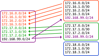
Enabling VRF Route Import and Export
Our final task is to configure route import and export among the Red, Green, and Shared VRFs. VRF route import and export are configured as two explicit, independent functions. Under VRFs Red and Green, we need to:
- Export local routes
- Import routes from VRF Shared
Under VRF Shared:
- Export local routes
- Import routes from VRFs Red and Green
To do this, we configure each VRF with import and export route targets. A route target is similar in format to a route distinguisher, but serves a different purpose. Whereas any given VRF route in our scenario has exactly one route distinguisher to uniquely identify it, a route can have zero or more route targets as arbitrary identifiers for reference by import and export policies. This allows for much greater flexibility than if only the route distinguisher was used. Although used only locally in our example, route targets are communicated with MP-BGP neighbors as extended communities.
Route targets can be defined in the same formats as route distinguishers. Here each route target will reuse the same format and value of its VRF's route distinguisher, just to keep things simple. However, remember that there is no direct relation between the two. Additionally, although each VRF is exporting only one route-target in our example, multiple route-targets can be exported simultaneously (resulting in multiple communities attached to an MP-BGP route).
ip vrf Blue
 rd 65000:3
!
ip vrf Green
 rd 65000:2
 route-target export 65000:2
 route-target import 65000:99
!
ip vrf Red
 rd 65000:1
 route-target export 65000:1
 route-target import 65000:99
!
ip vrf Shared
 rd 65000:99
 route-target export 65000:99
 route-target import 65000:1
 route-target import 65000:2
Now VRF Shared has routes from VRFs Red and Green, and VRFs Red and Green each have the route from VRF Shared (it may take a minute for the routes to appear in the table):
S1# show ip route vrf Shared

Routing Table: Shared
...

172.17.0.0/16 is variably subnetted, 2 subnets, 2 masks
B       172.17.1.0/30 is directly connected, 00:00:24, FastEthernet0/3
B       172.17.0.0/24 is directly connected, 00:00:24, Vlan17
     172.16.0.0/16 is variably subnetted, 2 subnets, 2 masks
B       172.16.0.0/24 is directly connected, 00:00:24, Vlan16
B       172.16.1.0/30 is directly connected, 00:00:24, FastEthernet0/1
C    192.168.99.0/24 is directly connected, Loopback99
S1# show ip route vrf Red

Routing Table: Red
...

172.16.0.0/16 is variably subnetted, 4 subnets, 2 masks
C       172.16.0.0/24 is directly connected, Vlan16
C       172.16.1.0/30 is directly connected, FastEthernet0/1
O       172.16.2.0/24 [110/2] via 172.16.0.2, 00:05:38, Vlan16
O       172.16.3.0/24 [110/2] via 172.16.0.3, 00:05:38, Vlan16
B    192.168.99.0/24 is directly connected, 00:00:44, Loopback99
S1# show ip route vrf Green

Routing Table: Green
...

172.17.0.0/16 is variably subnetted, 3 subnets, 2 masks
C       172.17.1.0/30 is directly connected, FastEthernet0/3
C       172.17.0.0/24 is directly connected, Vlan17
O       172.17.2.0/24 [110/2] via 172.17.0.2, 00:05:43, Vlan17
B    192.168.99.0/24 is directly connected, 00:00:49, Loopback99
VRF Blue, however, still contains only its own routes, as we did not configure import or export for this VRF:
S1# show ip route vrf Blue

Routing Table: Blue
...

172.18.0.0/16 is variably subnetted, 3 subnets, 2 masks
O       172.18.3.0/24 [110/2] via 172.18.0.3, 00:06:02, Vlan18
C       172.18.0.0/24 is directly connected, Vlan18
C       172.18.1.0/30 is directly connected, FastEthernet0/5
Lastly, we need to configure the VRF OSPF processes to redistribute BGP-learned routes to OSPF peers on S1:
S1(config)# router ospf 1 vrf Red
S1(config-router)# redistribute bgp 65000 subnets
S1(config-router)# router ospf 2 vrf Green
S1(config-router)# redistribute bgp 65000 subnets
These routes are now propagated via OSPF to S2 and S3 within their respective VRFs. On S3, we can verify that VLAN 316 (VRF Red) has access to the VOIP network, but VLAN 318 (VRF Blue) does not:
S3# show ip route vrf Red

Routing Table: Red
...

172.16.0.0/16 is variably subnetted, 4 subnets, 2 masks
C       172.16.0.0/24 is directly connected, Vlan16
O       172.16.1.0/30 [110/2] via 172.16.0.1, 00:10:15, Vlan16
O       172.16.2.0/24 [110/2] via 172.16.0.2, 00:10:15, Vlan16
C       172.16.3.0/24 is directly connected, Vlan316
O E2 192.168.99.0/24 [110/1] via 172.16.0.1, 00:10:15, Vlan16
S3# show ip route vrf Blue

Routing Table: Blue
...

172.18.0.0/16 is variably subnetted, 3 subnets, 2 masks
C       172.18.3.0/24 is directly connected, Vlan318
C       172.18.0.0/24 is directly connected, Vlan18
O       172.18.1.0/30 [110/2] via 172.18.0.1, 00:25:17, Vlan18
S3# ping vrf Red 192.168.99.1 source vlan316

Type escape sequence to abort.
Sending 5, 100-byte ICMP Echos to 192.168.99.1, timeout is 2 seconds:
Packet sent with a source address of 172.16.3.1
!!!!!
Success rate is 100 percent (5/5), round-trip min/avg/max = 1/3/4 ms
S3# ping vrf Blue 192.168.99.1 source vlan318

Type escape sequence to abort.
Sending 5, 100-byte ICMP Echos to 192.168.99.1, timeout is 2 seconds:
Packet sent with a source address of 172.18.3.1
.....
Success rate is 0 percent (0/5)
The final configurations of all three switches are made available here:
Comments
March 29, 2010 at 6:19 a.m. UTC
There is another way to configure route leaking between VRFs. Use GRE tunnel (from one VRF to another). This feature is unsupported, but it works. Very useful in some cases. You can find sample in my blog.
March 29, 2010 at 6:53 a.m. UTC
It is possible to avoid route export/import between VRFs by creating a seperate internetwork for inter-vrf communication (one end of a link belongs to one vrf, other end to another vrf), but this would not scale well.
March 29, 2010 at 3:15 p.m. UTC
Stretch,
How did you configure a multilayer switch in GNS? I'm only able to get 3700,2600,7200's with limited module support working. (i just downloaded GNS3 and installed it of course)
March 29, 2010 at 5:36 p.m. UTC
http://packetlife.net/blog/2009/apr/30/intro-vrf-lite/
How come in your first VRF article you did not a route distinguisher?
-Thanks
March 29, 2010 at 5:59 p.m. UTC
Sorry to double comment, I have two more questions.
-
You used passive interface commands on the vlan interfaces during OSPF configuration, how can the adjacency still be forming?
-
If I am understanding this correctly (may not be), BGP-MP was used to facilitate communication between the three VRF's. Why then was it necessary to export and import the VRF routes?
Thank you for the assistance.
March 29, 2010 at 8:05 p.m. UTC
@Rob: Who said anything about GNS3? These are real switches.
@ZeroZeroFourteen: 1) I probably should have, but it didn't seem necessary for that lab. 2) Look closely at which interfaces have been designated as passive. 3) How would MP-BGP know which routes to import and export if we don't tell it?
March 29, 2010 at 9:12 p.m. UTC
router ospf 1 vrf Red
 network 0.0.0.0 255.255.255.255 area 0
 passive-interface Vlan216
!
router ospf 2 vrf Green
 network 0.0.0.0 255.255.255.255 area 0
 passive-interface Vlan217

Interface 216 is the Red vlan
Interface 217 is the Green vlan
What the configuration appears to be doing (to me) is turning off OSPF on the Red VLAN on the Red VRF and allowing Green updates on the Red VRF. Similarly on the Green VRF the Green Vlan is made passive but the red is allowed.
I thought that the opposite would need to be configured, on the Red VRF the Green VLAN should be made passive, not the red. What am I missing?
With regards to BGP-MP from the routing output BGP seems to be seeing everything without the import/export statements.
S1# show ip bgp vpnv4 all
BGP table version is 47, local router ID is 192.0.2.1
Status codes: s suppressed, d damped, h history, * valid, > best, i - internal,
              r RIB-failure, S Stale
Origin codes: i - IGP, e - EGP, ? - incomplete

Network          Next Hop            Metric LocPrf Weight Path
Route Distinguisher: 65000:1 (default for vrf Red)
*> 172.16.0.0/24    0.0.0.0                  0         32768 ?
*> 172.16.1.0/30    0.0.0.0                  0         32768 ?
*> 172.16.2.0/24    172.16.0.2               2         32768 ?
*> 172.16.3.0/24    172.16.0.3               2         32768 ?
Route Distinguisher: 65000:2 (default for vrf Green)
*> 172.17.0.0/24    0.0.0.0                  0         32768 ?
*> 172.17.1.0/30    0.0.0.0                  0         32768 ?
*> 172.17.2.0/24    172.17.0.2               2         32768 ?
Route Distinguisher: 65000:3 (default for vrf Blue)
*> 172.18.0.0/24    0.0.0.0                  0         32768 ?
*> 172.18.1.0/30    0.0.0.0                  0         32768 ?
*> 172.18.3.0/24    172.18.0.3               2         32768 ?
Route Distinguisher: 65000:99 (default for vrf Shared)
*> 192.168.99.0     0.0.0.0                  0         32768 ?
The only thing I can think of id that even though BGP sees everything, it will not route between the VRF's without the import/export statements. Is that a correct understanding?
Thank you for taking the time to help me understand this, appreciate all the hard work you put into these blogs.
March 29, 2010 at 9:21 p.m. UTC
@Guest: Those are the user VLANs, not the transit VLANs (16, 17, and 18). And that output of show ip bgp vpnv4 all shows only the routes within respective VRFs of origin. Nothing has been imported/exported between VRFs at that point.
March 30, 2010 at 12:47 a.m. UTC
Great post. Never done anything like this before, very cool.
March 30, 2010 at 8:39 a.m. UTC
"Stretch,
How did you configure a multilayer switch in GNS? I'm only able to get 3700,2600,7200's with limited module support working. (i just downloaded GNS3 and installed it of course)"
Jeremy did this with 3550s as he's said, but you can achieve this in Dynamips/GNS3, using switch modules in the routers to trunk Vlan's between them.
If there's any call for it, I can upload the configuration I used to test this, along with the .net file too? It's not much different from the article, but there are subtle differences for how you'll have to configure everything.
March 30, 2010 at 8:39 a.m. UTC
@Stretch ok that makes sense.
One thing that is still baffling me is how come when you do your import/export statements, the routes go into BGP and not OSPF (and thus are later manually redistributed)?
March 30, 2010 at 11:31 a.m. UTC
"@Stretch ok that makes sense.
One thing that is still baffling me is how come when you do your import/export statements, the routes go into BGP and not OSPF (and thus are later manually redistributed)?"
I'm not 100% sure on this, Stretch can confirm, but I would take that to be the Redistribute Connected command. For example: -
address-family ipv4 vrf Red
  redistribute connected
  redistribute ospf 1 vrf Red
  no synchronization
Would then take everything that is in the ospf process for that vrf, and also take in anything which is a connected interface with the ip vrf forwarding Red command. You could do that with OSPF, but then you'd get routes picked up that you don't necessarily want, and it also makes it harder to redistribute I'm guessing.
March 30, 2010 at 11:40 a.m. UTC
Actually ignore my last comment, I got the wrong end of the stick...
After a little googling, I think the route-target is a BGP specific command, which ports the routes out into a BGP community, so in a sense the routes are being exported, but not out to the global VRF, just to an arbitrary location, to then be imported in the other instances within BGP.
Hopefully Jeremy can clarify this.
March 30, 2010 at 2:34 p.m. UTC
@Stuh84 - I would be very much interested in your .net and configs for this in GNS3. Thank you.
March 31, 2010 at 8:20 a.m. UTC
http://www.box.net/shared/akz8tyd235
If you go there, it has my configurations and the .net file.
Couple of pointers for you to get it all working
1) Obviously change specific settings for your host (idlepc, IOS location etc)
2) Create vlans on each device which needs them, for example, on R1 (S1 in the original article), you need to do the following
From enable mode: -

R1#vlan database
R1(vlan)#vlan 16
R1(vlan)#vlan 17
R1(vlan)#vlan 18
You'd do the same on R2 and R3 (to create the 216, 217 and 218 VLANs where required, as well as the 16, 17 and 18 VLANs)
If you have any issues, let me know.
July 23, 2010 at 3:00 p.m. UTC
What is happened if RED and GREEN has same IP Address and they both need to access VOIP segment.
Consider condition where we couldn't drive Customer IP Address.
Br,
Heri
August 2, 2010 at 8:49 a.m. UTC
The coolest i have seen on the subject. better than what i saw on cisco site.
November 9, 2010 at 1:58 p.m. UTC
Nice one Switch. TBH I'm not that good with MLS so far hence creating SVI's wasn't something I understand too well in this config. It would have been much more straight forward for me had there been an All router environment. Regardless, it looks like a great config. So let me try to get this right; what you're trying to do here is advertise the connected loopback interface from S1's Shared VRF to VRF RED on S2 or S3 via OSPF then redistribute it into BGP on S2 or S3 and then send it across back to VRF RED on S1? Can you advertise routes from one VRF on the same router or switch to another VRF without the prefix exiting from any interface and if so whats that technology called? Would that technology by any cahnce be called Route leaking?
November 19, 2010 at 8:28 p.m. UTC
Very good explanations...I got more from this than from Cisco's documentation. Bravo, Jeremy.
December 27, 2010 at 3:39 a.m. UTC
I should have known packetlife.net earlier, my knowledge of vrf owes to you Mr. Jeremy :) Thanks for the write up, my first exposure to VRF was when I was reading another post from your blog (not this one), I was thinking of an alternative viable solution to PBR for doing path control and I came across your post about VRF. thanks again for sharing. :)
April 11, 2011 at 10:32 p.m. UTC
good article ;)
April 21, 2011 at 12:32 a.m. UTC
Hi MAte,
whats to stop green from accessing red via purple?
April 24, 2011 at 2:33 a.m. UTC
Where exactly can I get this multi-vlan this in a integrated design? I know mpls/vpn design separately and i know vlan routing too. Just never worked with the designs with everything else in. I saw an article somewhere where one guy used central services vpn design, without importing/exporting b2n diff. vrf - but instead using a firewall to switch/swap the vrfs?
How cool...
BNM
June 8, 2011 at 9:58 a.m. UTC
Totally get this where there is a core switch that can be used to exchange the vrf routes via BGP. My question; is there a way to leak routes between vrfs within a single switch. I have a source that is within the global routing table and a destination that is within a vrf on the same device. How can i leak routes between them?
June 21, 2011 at 6:39 p.m. UTC
Interfaces 1, 3, and 5 on S1 have IPs with a /30 subnet mask, but the other devices have /24s on the matching L3 interfaces. Any special reason?
September 3, 2011 at 3:48 a.m. UTC
This is beautiful blog..Congrats!!
Can you also guide for a secenerio, when there is overlapping address in multiple customer vrf and we have to configure a shared service for them.
September 7, 2011 at 11:22 a.m. UTC
Very good and clean article. You should organize your blog articles systematically into a book. I'll be the first buyer ;)..
October 31, 2011 at 4:04 p.m. UTC
My question is similar to Anshu_anr's. What happends when you have VRF Red and VRF Green both with the same routes in their tables? IE. Red has 10 sites within its MPLS bubble and Green has 10 within its bubble. Now both are using the same 192.168.x.x scheme. What would that do to the route table when you redistributed it into EIGRP or OSPF?
November 14, 2011 at 4:32 p.m. UTC
Very good article. and very well explained !
A quick question on redistribution. Do we have to use MP-BGP or static routing to communicate between vrf and global ? I'm trying to redistribute between between two OSPF domains/processes (global(process1) and the vrf(process 66) using the redistribute command. i get the following error when configure.
annex-d-data(config)#router os annex-d-data(config)#router ospf 1 annex-d-data(config-router)#red annex-d-data(config-router)#redistribute os annex-d-data(config-router)#redistribute ospf 66 sub annex-d-data(config-router)#redistribute ospf 66 subnets %VRF specified does not match this router
The vrf is created on the router. Any thoughts ?
Thanks.
December 17, 2011 at 7:28 p.m. UTC
Very good man !!!
May 9, 2012 at 11:19 p.m. UTC
Hi Jeremy Stretch,
I have one question and can you answer Quickly because my implementation is going on with VRF.
No my question is:
Suppose there is one more Loopback in S1 and my P.C is connected to S2 in the Red Vlan. So can i ping the loopback from my P.C as the loopback in the S1 is not assigned to any of the VRF
regards,
Nehal
May 16, 2012 at 10:15 a.m. UTC
Nice lab with clear explanation... I will try it. Thanks
May 31, 2012 at 12:27 a.m. UTC
Well written nicely explained. for the critics give a better explanation
September 9, 2012 at 12:03 p.m. UTC
thanx okeyyyyyyyyyyyyyyyyyy
September 9, 2012 at 12:04 p.m. UTC
thanx okeyyyyyyyyyyyyyyyyyy
November 30, 2012 at 7:08 p.m. UTC
Hello, Your article is really helpful to me...as I am working on the same scenario...thank you !!
December 18, 2012 at 7:46 p.m. UTC
Excellent article! Very helpful in understanding the basics of VRF Lite.
January 10, 2013 at 6:46 a.m. UTC
awsome!
January 17, 2013 at 4:21 p.m. UTC
Hi,
does this work in IPv6 (dual stack environment) ?
Thanks.
January 24, 2013 at 2:52 a.m. UTC
why is it that vpnv4 address family is not available in cisco 3550 or 3560s? From the topology S1, S2 and S3 is somewhat acting like a P/PE at the same time.
June 4, 2013 at 9:01 p.m. UTC
That was really helpful I had a similar case to work on and I tried static routes for vrf-lite leaking but unfortunately it didn't work. Thanks Jeremy!
June 19, 2013 at 4:27 a.m. UTC
Thx! Very helpful! I didn't understand the only thing of that. When it is necessary to specify rt, and when there is no.
August 26, 2013 at 7:41 p.m. UTC
Hi everyone,
Excuse my ignorance, but I am pretty new to MP-BGP and VRF technology.
My question is very simple, I am attempting to import a single host address from one VRF into another via MP-BGP.
I understand route-maps are used for granular filtering, however I have tried this using standard ACL, extended ACL and prefix list and it does not seems to work. However when I try importing/exporting the whole subnet the communication works as expected from one VRF into the other. Am I missing a trick?! Sample configs can be posted if required but is there a restriction in how BGP imports/exports?
Your help is very much appreciated.
December 31, 2013 at 11:33 a.m. UTC
Excellently explained with no hindrance.
Don't know why Cisco article follows the same pattern as yours.
Thanks Jeremy....!
April 10, 2014 at 9:11 a.m. UTC
Good explanation!!
Thanks Jeremy
April 13, 2014 at 1:49 p.m. UTC
Thanks Stretch, you make my life easier. I practice my lab from your blogs, and its great and I get to understand these concepts very well. You are my teacher from behind the curtain. :D
May 4, 2014 at 8:17 p.m. UTC
Hi,
In the above post you state:
'Here each route target will reuse the same format and value of its VRF's route distinguisher, just to keep things simple. However, remember that there is no direct relation between the two.'
Is there any link between RD 65000:2 and RT 65000:2?
If there is no correlation between the two how does BGP know which routes each RT refeerences and what to import/export?
May 11, 2014 at 10:11 p.m. UTC
"Is there any link between RD 65000:2 and RT 65000:2? If there is no correlation between the two how does BGP know which routes each RT references and what to import/export?"
All of the routes in the VRF are eligible to be imported. (as long as your matching an export configured either locally or on another router that is an iBGP VPNV4 peer) Filtering is done with import maps. I believe Jeremy has an article on this. There is no correlation. You need to come up with your own scheme for RD's and RT's.
My question is - Is there any way to bring up a VPNv4 neighborship with a router, on a 3550? I cant seem to - don't think it is possible.
June 18, 2014 at 9:37 a.m. UTC
thank you Jeremy for share your knowledge. GOOD LUCK
June 25, 2014 at 9:24 a.m. UTC
When this article was written true VRF-lite route leak was not available and BGP had to be used. BGP is natural in MPLS VPN VRF deployments but VRF-lite deployments typically do not have it. It would have been good to update the article with modern software practices in mind:
vrf definition XXX
 rd N:N
 !
 address-family ipv4
  route-replicate from vrf ...
July 17, 2014 at 9:38 p.m. UTC
Hi. That's an awesome article. I did not understand one thing, though: Why did you created two diffferent vlans for the same traffic? I mean, why are there a Vlan 16 and 216, vlan 17 and 217, vlan 18 and 218? It could all be 16, 17 and 18, or 216, 217 and 218.
Am I missing something, or was it just an unnecessary config?
August 14, 2014 at 7:00 a.m. UTC
SW2 and SW3 CEs need to have "capability vrf-lite" to disable OSPF DN bit check in order to get the "Shared" vrf routes.
September 14, 2014 at 5:05 p.m. UTC
Really usefull, exactly what i was searching, however, i'm really nervous to put these on a production environment because, this i need to put it into a remote datacenter and i barely know about BGP, the only thing i know is cbtnuggets CCNP, and a couple of simple labs i put but i really don't know how to thsoot this if one problem arise, can you tell me how often this crash, of common problems because as i said i need to put these in a remote datacenter. Thank you
March 31, 2015 at 1:05 p.m. UTC
I am new to BGP and VRF, so my question may sound naive to you. The question is, is the whole concept of Virtual routing and forwarding applicable only in the case of iBGP? Or does the concept applies to eBGP too?
June 26, 2015 at 6:57 a.m. UTC
Jeremy, it is possible to configure route leaking between VRFs without BGP using. Can we do this with OSPF only?
September 16, 2015 at 5:33 p.m. UTC
EVN is essentially VRF-LITE but with support for IGP route sharing and also does not require one sub-interface per VRF. It introduces the VNET TAG.
January 23, 2016 at 8:11 a.m. UTC
Stretch,
I think we need to enable "capability vrf-lite" , IF not "DN" bit will come in picture. I personally tried this topology and found that the voice notwork resides in SW2 routing database , but was not residing in OSPF routing table unless i enabled "capability vrf-lite".
Thanks.
April 25, 2016 at 6:35 p.m. UTC
Wooow Man, i guess you will be the super trainer.
Excellent article! Great! 5 Stars!
Last time i faced the exact issue trying to solve this problem for RNC GGSN GTP direct tunnel in the live network, but had no experience so decided to address differently. You have described each detail precisely.
Thank you.
June 15, 2016 at 4:19 a.m. UTC
Hi Strech,
I see you redistribute direct routes and ospf vrf red to bgp on S1, but I was wondering why in the vrf shared I couldn't see route such as 172.16.2.0/24, 172.16.3.0/24
S1# show ip route vrf Shared
Routing Table: Shared ...
172.17.0.0/16 is variably subnetted, 2 subnets, 2 masks B 172.17.1.0/30 is directly connected, 00:00:24, FastEthernet0/3 B 172.17.0.0/24 is directly connected, 00:00:24, Vlan17 172.16.0.0/16 is variably subnetted, 2 subnets, 2 masks B 172.16.0.0/24 is directly connected, 00:00:24, Vlan16 B 172.16.1.0/30 is directly connected, 00:00:24, FastEthernet0/1 C 192.168.99.0/24 is directly connected, Loopback99
July 25, 2016 at 8:34 p.m. UTC
Hi Stretch,
Thank you so much with this article Inter-VRF Routing with VRF Lite. I am new to this type of technology but the way you explained and step by step configurations made me realize how simply this technology is. Thank you so much for your effort in doing a wonderful job. It real helped me understand a lot of things. I real a appreciate it.
May God bless you!!!
kevynjr