The premiere source of truth powering network automation. Open and extensible, trusted by thousands.
NetBox is now available as a managed cloud solution! Stop worrying about your tooling and get back to building networks.
Multiple Spanning Tree (MST)
By stretch | Monday, April 26, 2010 at 5:29 p.m. UTC
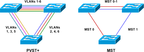
The default spanning tree mode on Cisco Catalyst switches is PVST+ or, on newer models, Rapid PVST+. These protocols result in a direct one-to-one mapping of spanning tree instances to VLANs (hence the term per-VLAN spanning tree). For example, if there exist eight VLANs on a switch, the switch must participate in eight independent spanning trees. This is often undesirable, as the number of actually unique spanning tree topologies is typically less than the number of VLANs (at worst, the two will be equal). Running only a single common spanning tree (CST, which is not supported on Cisco Catalyst switches) would be more efficient, but it does not allow for the design flexibility afforded by PVST.
Multiple Spanning Tree (MST) was created to allow for multiple spanning tree topologies while preserving scalability. MST enables an administrator to map an arbitrary number of VLANs to a single MST instance, resulting in the minimum number of instances needed to satisfy a design. If, for example, you have six VLANs but only two unique layer two topologies, you need only two MST instances.
MST Configuration
The topology below illustrates a common scenario wherein a layer two access switch carries four VLANs and has two uplinks to two distribution switches. Routed SVIs with HSRP have been configured on the distribution switches to provide redundant default gateways for the hosts in all four VLANs.
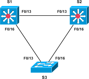
The base configuration for each of the three switches follows.
Base Configuration
S1
vlan 10
vlan 20
vlan 30
vlan 40
!
interface FastEthernet0/13
 switchport trunk encapsulation dot1q
 switchport mode trunk
!
interface FastEthernet0/16
 switchport trunk encapsulation dot1q
 switchport mode trunk
!
interface Vlan10
 ip address 192.168.10.1 255.255.255.0
 standby 10 ip 192.168.10.3
 standby 10 priority 110
 standby 10 preempt
 standby 10 track FastEthernet0/13 20
!
interface Vlan20
 ip address 192.168.20.1 255.255.255.0
 standby 20 ip 192.168.20.3
!
interface Vlan30
 ip address 192.168.30.1 255.255.255.0
 standby 30 ip 192.168.30.3
 standby 30 priority 110
 standby 30 preempt
 standby 30 track FastEthernet0/13 20
!
interface Vlan40
 ip address 192.168.40.1 255.255.255.0
 standby 40 ip 192.168.40.3
S2
vlan 10
vlan 20
vlan 30
vlan 40
!
interface FastEthernet0/13
 switchport trunk encapsulation dot1q
 switchport mode trunk
!
interface FastEthernet0/16
 switchport trunk encapsulation dot1q
 switchport mode trunk
!
interface Vlan10
 ip address 192.168.10.2 255.255.255.0
 standby 10 ip 192.168.10.3
!
interface Vlan20
 ip address 192.168.20.2 255.255.255.0
 standby 20 ip 192.168.20.3
 standby 20 priority 110
 standby 20 preempt
 standby 20 track FastEthernet0/13 20
!
interface Vlan30
 ip address 192.168.30.2 255.255.255.0
 standby 30 ip 192.168.30.3
!
interface Vlan40
 ip address 192.168.40.2 255.255.255.0
 standby 40 ip 192.168.40.3
 standby 40 priority 110
 standby 40 preempt
 standby 40 track FastEthernet0/13 20
S3
vlan 10
vlan 20
vlan 30
vlan 40
!
interface FastEthernet0/13
 switchport trunk encapsulation dot1q
 switchport mode trunk
!
interface FastEthernet0/16
 switchport trunk encapsulation dot1q
 switchport mode trunk
On S3, access ports should be assigned to VLANs as appropriate.
We can see that by default a PVST+ instance is created automatically for every VLAN:
S1# show spanning-tree summary
Switch is in pvst mode
Root bridge for: none
Extended system ID           is enabled
Portfast Default             is disabled
PortFast BPDU Guard Default  is disabled
Portfast BPDU Filter Default is disabled
Loopguard Default            is disabled
EtherChannel misconfig guard is enabled
UplinkFast                   is disabled
BackboneFast                 is disabled
Configured Pathcost method used is short

Name                   Blocking Listening Learning Forwarding STP Active
---------------------- -------- --------- -------- ---------- ----------
VLAN0001                     1         0        0          1          2
VLAN0010                     1         0        0          1          2
VLAN0020                     1         0        0          1          2
VLAN0030                     1         0        0          1          2
VLAN0040                     1         0        0          1          2
---------------------- -------- --------- -------- ---------- ----------
5 vlans                      5         0        0          5         10
MST Configuration
We need to configure two MST instances on each of the three switches, both of which will carry two access VLANs. This is done in MST configuration mode. All VLANs are assigned to MST instance 0 by default, so we only need to define a second instance to carry VLANs 20 and 40.
S1(config)# spanning-tree mst configuration
S1(config-mst)# show current
Current MST configuration
Name      []
Revision  0     Instances configured 1

Instance  Vlans mapped
--------  ---------------------------------------------------------------------
0         1-4094
-------------------------------------------------------------------------------
S1(config-mst)# instance 1 vlan 20,40
S1(config-mst)# show pending
Pending MST configuration
Name      []
Revision  0     Instances configured 2

Instance  Vlans mapped
--------  ---------------------------------------------------------------------
0         1-19,21-39,41-4094
1         20,40
-------------------------------------------------------------------------------
Next, we assign a region name and revision number. These are used to identify switches as belonging to a common MST region.
S1(config-mst)# name Region1
S1(config-mst)# revision 1
S1(config-mst)# exit
Exiting MST configuration mode will apply the changes; to exit MST configuration without applying the changes, use abort.
These configurations must be applied to all three switches. The final MST configuration looks like this:
spanning-tree mst configuration
 name Region1
 revision 1
 instance 1 vlan 20, 40
We'll configure S1 to become the root for instance 0 (VLANs 10 and 30), and S2 will be the root for instance 1 (VLANs 20 and 40):
S1(config)# spanning-tree mst 0 priority 0
S1(config)# spanning-tree mst 1 priority 4096
S2(config)# spanning-tree mst 0 priority 4096
S2(config)# spanning-tree mst 1 priority 0
Finally, we change the spanning tree mode from the default of PVST+ to MST on all three switches:
S1(config)# spanning-tree mode mst
S2(config)# spanning-tree mode mst
S3(config)# spanning-tree mode mst
Finally, we can verify that we now have two MST instances forming our two L2 topologies as intended:
S3# show spanning-tree mst

##### MST0    vlans mapped:   1-19,21-39,41-4094
Bridge        address 000e.8316.f500  priority      32768 (32768 sysid 0)
Root          address 0013.c412.0f00  priority      0     (0 sysid 0)
              port    Fa0/13          path cost     0
Regional Root address 0013.c412.0f00  priority      0     (0 sysid 0)
                                      internal cost 200000    rem hops 19
Operational   hello time 2 , forward delay 15, max age 20, txholdcount 6
Configured    hello time 2 , forward delay 15, max age 20, max hops    20

Interface        Role Sts Cost      Prio.Nbr Type
---------------- ---- --- --------- -------- --------------------------------
Fa0/13           Root FWD 200000    128.13   P2p
Fa0/16           Altn BLK 200000    128.16   P2p

##### MST1    vlans mapped:   20,40
Bridge        address 000e.8316.f500  priority      32769 (32768 sysid 1)
Root          address 000f.345f.1680  priority      1     (0 sysid 1)
              port    Fa0/16          cost          200000    rem hops 19

Interface        Role Sts Cost      Prio.Nbr Type
---------------- ---- --- --------- -------- --------------------------------
Fa0/13           Altn BLK 200000    128.13   P2p
Fa0/16           Root FWD 200000    128.16   P2p
Posted in Switching
Comments
April 26, 2010 at 6:20 p.m. UTC
Hey Jeremy, first - excellent write up. I do have a question about the configuration from existing PSVT+ to MST migration...
During BCMSN studies I've read that going from PVST+ to rapid-PVST did not require you to disable spanning tree features that were built into rapid spanning tree such as port-fast and backbone fast - basically rapid-pvst will use the configs for pvst+.
At the same time this article shows that if backbonefast & portfast is enabled for PSVT+ and you migrate to rapid-pvst, those configs actually get ignored (therefore article shows which features to disable.)
Would it be the same for MST since MST has portfast and backbonefast built in like rapid-pvst?
April 26, 2010 at 7:01 p.m. UTC
It's always helpful when using MST to validate the digest on all switches in a region: "show spanning-tree mst configuration mst". If your MST config is identical on all the switches of a region, then the digest must match. This can be really problematic if you have a large number of switches deployed in a region with hundreds or thousands of VLANs in use. Generally, a mismatch in digests indicates the VLAN lists are not matched.
Also important to note that any VLAN assignment to MST regions can include VLANs not found in the tree, but should be prepopulated with the VLANs assigned (including any future expansion).
Nice writeup, as usual.
April 26, 2010 at 9:07 p.m. UTC
Nice article and a good explanation on MST, but about the HSRP configuration. I always configure one switch as the master HSRP router. In the example above you have configured asymmetric HSRP routing. This configuration could result in the flooding of unicast traffic.
I ones read an article about this. I found the article again after some research on the internet, maybe it could be useful:
http://www.cisco.com/en/US/tech/tk648/tk362/technologies_tech_note09186a0080094afd.shtml#t8
April 26, 2010 at 11:12 p.m. UTC
You will need VTPv3 in order to propagate database information, AFAIK.
Also, an "allowed vlan" setting might (will?) blackhole traffic.
April 27, 2010 at 4:48 p.m. UTC
Great article, as always. Thanks!
April 28, 2010 at 6:51 a.m. UTC
Hello,
If I remember correctly, MST causes the spanning tree to reset and recalculate, when you add VLANs to it, resulting in the proposal to pre-populate the MST instances. I never had the time to lab it, so a comment on this would be welcome.
regards,
Phil
June 14, 2010 at 3:55 p.m. UTC
Phil, a bit late reading this but I learned the hard way that adding a VLAN will cause a re-calcuation of the MST instance. This caused a bit of downtime for me; I've since changed my configuration so that critical network traffic has its own MST instance.
In my case,
Instance 0 = VLANs that we aren't actually using
Instance 1 = VLANs that we use for everyday use (voice, desktop, etc)
Instance 2 = VLANs that carry critical PLC data for collection
MST00 vlans mapped: 1,7-14,16-19,24-29,31-39,41-49,51-99
101-199,201-4094
MST01 vlans mapped: 2-4,6,15,20-23,30,40,50,100,200
MST02 vlans mapped: 5
April 4, 2014 at 4:54 p.m. UTC
Your are unique in the world. Superb articles...
June 25, 2014 at 1:37 a.m. UTC
Do a blog on mst with mutliple regions and see how you get on. I find that concept hard to grasp
February 22, 2015 at 10:54 a.m. UTC
I have a network with around 15 rings, with same number of VLAN's, each ring having more than 25 L2 switches, most of them not Cisco. They support MSTP.
Core Switch is 4500 series, and we are planning to put 2 fiber links for each ring.
How can i go forward here? Can i use MSTP on all the switches?
Could you please give me a starter idea for me to get going here.