The premiere source of truth powering network automation. Open and extensible, trusted by thousands.
NetBox is now available as a managed cloud solution! Stop worrying about your tooling and get back to building networks.
Intro to VRF lite
By stretch | Thursday, April 30, 2009 at 3:08 a.m. UTC
VRFs, or VPN Routing and Forwarding instances, are most commonly associated with MPLS service providers. In such networks, MPLS encapsulation is used to isolate individual customers' traffic and an independent routing table (VRF) is maintained for each customer. Most often, MP-BGP is employed to facilitate complex redistribution schemes to import and export routes to and from VRFs to provide Internet connectivity.
However, VRF configuration isn't at all dependent on MPLS (the two components just work well together). In Cisco terminology, deployment of VRFs without MPLS is known as VRF lite, and this article discusses a scenario where such a solution could come in handy.
Assume the topology illustrated below is a network owned by an enterprise. As you would expect, normal company traffic must pass through the firewall so that company policy can be enforced. However, this a secondary Internet connection has been added to this network: an unrestricted ADSL circuit designated for guests visiting the company campus. The 10.0.0.0/16 network is used for trusted traffic, and 192.168.0.0/16 is used for guest traffic.
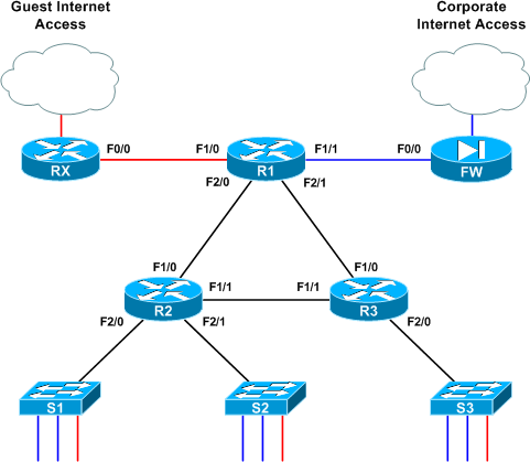
All router interfaces which provide transport for both types of traffic have been configured with two subinterfaces performing 802.1Q encapsulation; .10 for VLAN 10 (blue) and .20 for VLAN 20 (red). Note that although 802.1Q encapsulation is used to tag frames across the link, each link is a routed segment with an IP interface at either end. For example, here is R1's F2/0 configuration (the complete config of all three core routers is attached at the end of the article if you'd like to skip ahead):
interface FastEthernet2/0
 description R2
 no ip address
!
interface FastEthernet2/0.10
 encapsulation dot1Q 10
 ip address 10.0.12.1 255.255.255.252
!
interface FastEthernet2/0.20
 encapsulation dot1Q 20
 ip address 192.168.12.1 255.255.255.252
If this were a generic routed network, the network admin would be busy touching up his or her resume right now. Obviously, the addition of a "back door" Internet access link opens a huge security hole, but we can employ VRFs here to segment the single physical infrastructure into two virtual, isolated networks. VRFs employ essentially the same concept as VLANs and trunking, but at layer three.
VRF lite is simple: each routed interface (whether physical or virtual) belongs to exactly one VRF. Unless import/export maps have been applied, routes (and therefore packets) cannot move from one VRF to another, much like the way VLANs work at layer two. Packets entering VRF A can only follow routes in routing table A, as we'll see shortly.
Prior to VRF configuration, all routers have all of their connected routes in the global routing table as you would expect:
R1# show ip route
Codes: C - connected, S - static, R - RIP, M - mobile, B - BGP
   D - EIGRP, EX - EIGRP external, O - OSPF, IA - OSPF inter area
   N1 - OSPF NSSA external type 1, N2 - OSPF NSSA external type 2
   E1 - OSPF external type 1, E2 - OSPF external type 2
   i - IS-IS, su - IS-IS summary, L1 - IS-IS level-1, L2 - IS-IS level-2
   ia - IS-IS inter area, * - candidate default, U - per-user static route
   o - ODR, P - periodic downloaded static route

Gateway of last resort is not set

192.168.12.0/30 is subnetted, 1 subnets
    C       192.168.12.0 is directly connected, FastEthernet2/0.20
 192.168.13.0/30 is subnetted, 1 subnets
    C       192.168.13.0 is directly connected, FastEthernet2/1.20
 10.0.0.0/30 is subnetted, 3 subnets
    C       10.0.12.0 is directly connected, FastEthernet2/0.10
    C       10.0.13.0 is directly connected, FastEthernet2/1.10
    C       10.0.0.0 is directly connected, FastEthernet1/1
 192.168.0.0/30 is subnetted, 1 subnets
    C       192.168.0.0 is directly connected, FastEthernet1/0
To begin, let's create VRFs BLUE and RED on R1:
R1(config)# ip vrf BLUE
R1(config-vrf)# description Trusted Traffic
R1(config-vrf)# ip vrf RED
R1(config-vrf)# description Guest Traffic
Certainly not the most challenging of tasks, eh? Next, we'll add interface F1/0 (which connects to the guest-use ADSL uplink) to VRF RED:
R1(config)# int f1/0
R1(config-if)# ip vrf forwarding RED
% Interface FastEthernet1/0 IP address 192.168.0.2 removed due to enabling VRF RED
Wait a tick, what just happened? When assigning an interface to a VRF, IOS automatically deletes any preconfigured IP address to remove that route from the global table. Now when an IP address is assigned to this interface, its network gets added to the specific routing table for that VRF.
So, we reapply our IP to F1/0 and verify that its configuration is complete:
R1(config-if)# ip add 192.168.0.2 255.255.255.252
R1(config-if)# ^Z
R1# show run interface f1/0
Building configuration...
Current configuration : 137 bytes
!
interface FastEthernet1/0
 description RX
 ip vrf forwarding RED
 ip address 192.168.0.2 255.255.255.252
 duplex auto
 speed auto
end
But look at our routing table now:
R1# show ip route
[...]

192.168.12.0/30 is subnetted, 1 subnets
    C       192.168.12.0 is directly connected, FastEthernet2/0.20
 192.168.13.0/30 is subnetted, 1 subnets
    C       192.168.13.0 is directly connected, FastEthernet2/1.20
 10.0.0.0/30 is subnetted, 3 subnets
    C       10.0.12.0 is directly connected, FastEthernet2/0.10
    C       10.0.13.0 is directly connected, FastEthernet2/1.10
    C       10.0.0.0 is directly connected, FastEthernet1/1
The 192.168.0.0/30 route is gone from the global table; it now resides in the VRF RED table, which we have to inspect separately by appending the vrf argument to show ip route:
R1# show ip route vrf RED
[...]

192.168.0.0/30 is subnetted, 1 subnets
    C       192.168.0.0 is directly connected, FastEthernet1/0
As you can imagine, this extra step of reapplying an IP address must be repeated for every interface we add to a VRF. I'll spare you the monotony of line-by-line configs and instead present the relevant finished configuration of R1:
interface FastEthernet1/0
 description RX
 ip vrf forwarding RED
 ip address 192.168.0.2 255.255.255.252
!
interface FastEthernet1/1
 description FW
 ip vrf forwarding BLUE
 ip address 10.0.0.2 255.255.255.252
!
interface FastEthernet2/0
 description R2
 no ip address
!
interface FastEthernet2/0.10
 encapsulation dot1Q 10
 ip vrf forwarding BLUE
 ip address 10.0.12.1 255.255.255.252
!
interface FastEthernet2/0.20
 encapsulation dot1Q 20
 ip vrf forwarding RED
 ip address 192.168.12.1 255.255.255.252
!
interface FastEthernet2/1
 description R3
 no ip address
!
interface FastEthernet2/1.10
 encapsulation dot1Q 10
 ip vrf forwarding BLUE
 ip address 10.0.13.1 255.255.255.252
!
interface FastEthernet2/1.20
 encapsulation dot1Q 20
 ip vrf forwarding RED
 ip address 192.168.13.1 255.255.255.252
As all interfaces now belong to isolated VRFs, our global routing table is completely empty. We can verify that all 10.0.0.0/16 routes are stored in VRF BLUE, and all 192.168.0.0/16 routes are stored in VRF RED:
R1# show ip route vrf BLUE

Routing Table: BLUE
[...]

10.0.0.0/30 is subnetted, 3 subnets
    C       10.0.12.0 is directly connected, FastEthernet2/0.10
    C       10.0.13.0 is directly connected, FastEthernet2/1.10
    C       10.0.0.0 is directly connected, FastEthernet1/1
R1# show ip route vrf RED

Routing Table: RED
[...]

192.168.12.0/30 is subnetted, 1 subnets
    C       192.168.12.0 is directly connected, FastEthernet2/0.20
 192.168.13.0/30 is subnetted, 1 subnets
    C       192.168.13.0 is directly connected, FastEthernet2/1.20
 192.168.0.0/30 is subnetted, 1 subnets
    C       192.168.0.0 is directly connected, FastEthernet1/0
At this point, although only R1 has been configured with VRFs, it can still route traffic to R2 and R3 with no problem. This is because, like VLANs, VRFs are only locally significant to the router.
After tediously configuring VRFs on the other two routers in the same manner, we can now configure our IGP. For this example, we'll be running an OSPF instance per VRF. We do this by appending the vrf argument to each router statement:
R1(config)# router ospf 1 vrf BLUE
R1(config-router)# router-id 0.0.1.1
R1(config-router)# network 10.0.0.0 0.0.255.255 area 0
R1(config-router)# router ospf 2 vrf RED
R1(config-router)# router-id 0.0.1.2
R1(config-router)# network 192.168.0.0 0.0.255.255 area 0
These are completely independent OSPF processes; as such, a unique router ID must be used for each. (If you're used to using IPv4 addresses as router ID, the IDs used above might seem strange. Remember that the OSPF router ID is in fact an arbitrary 32-bit value simply expressed in dotted-decimal. Here, the third "octet" represents the router number and the fourth octet represents the VRF.)
After configuring the other two routers with two OSPF processes each, we see two adjacencies formed per link, one per VRF:
R1# show ip ospf neighbor

Neighbor ID     Pri   State           Dead Time   Address         Interface
0.0.3.2           1   FULL/DR         00:00:39    192.168.13.2    FastEthernet2/1.20
0.0.2.2           1   FULL/DR         00:00:39    192.168.12.2    FastEthernet2/0.20
0.0.3.1           1   FULL/DR         00:00:31    10.0.13.2       FastEthernet2/1.10
0.0.2.1           1   FULL/DR         00:00:32    10.0.12.2       FastEthernet2/0.10
Assuming our edge routers aren't running OSPF, we'll also create two static default routes on R1, one for each VRF:
R1(config)# ip route vrf BLUE 0.0.0.0 0.0.0.0 10.0.0.1
R1(config)# ip route vrf RED 0.0.0.0 0.0.0.0 192.168.0.1
By now you've probably deduced that VRF configuration mostly consists of appending a vrf keyword to certain commands where appropriate. Unfortunately the argument isn't inserted at the same point in all commands, so it may take a few queries of the context-sensitive help before you get them all down.
We can verify that our static routes exist along with their OSPF-leanred companions in their respective VRFs:
R1# show ip route vrf BLUE

Routing Table: BLUE
[...]

10.0.0.0/8 is variably subnetted, 7 subnets, 2 masks
    C       10.0.12.0/30 is directly connected, FastEthernet2/0.10
    C       10.0.13.0/30 is directly connected, FastEthernet2/1.10
    O       10.0.2.0/24 [110/2] via 10.0.12.2, 00:04:52, FastEthernet2/0.10
    O       10.0.3.0/24 [110/2] via 10.0.13.2, 00:04:52, FastEthernet2/1.10
    C       10.0.0.0/30 is directly connected, FastEthernet1/1
    O       10.0.1.0/24 [110/2] via 10.0.12.2, 00:04:52, FastEthernet2/0.10
    O       10.0.23.0/30 [110/2] via 10.0.13.2, 00:04:52, FastEthernet2/1.10
                 [110/2] via 10.0.12.2, 00:04:52, FastEthernet2/0.10
S*   0.0.0.0/0 [1/0] via 10.0.0.1
R1# show ip route vrf RED

Routing Table: RED
[...]

192.168.12.0/30 is subnetted, 1 subnets
    C       192.168.12.0 is directly connected, FastEthernet2/0.20
 192.168.13.0/30 is subnetted, 1 subnets
    C       192.168.13.0 is directly connected, FastEthernet2/1.20
 192.168.23.0/30 is subnetted, 1 subnets
    O       192.168.23.0 [110/2] via 192.168.13.2, 00:04:16, FastEthernet2/1.20
                 [110/2] via 192.168.12.2, 00:04:16, FastEthernet2/0.20
 192.168.0.0/30 is subnetted, 1 subnets
    C       192.168.0.0 is directly connected, FastEthernet1/0
    O    192.168.1.0/24 [110/2] via 192.168.12.2, 00:04:16, FastEthernet2/0.20
    O    192.168.2.0/24 [110/2] via 192.168.12.2, 00:04:16, FastEthernet2/0.20
    O    192.168.3.0/24 [110/2] via 192.168.13.2, 00:04:17, FastEthernet2/1.20
S*   0.0.0.0/0 [1/0] via 192.168.0.1
Finally we just need to advertise a default route in both OSPF processes from R1 so R2 and R3 can learn them:
R1(config)# router ospf 1
R1(config-router)# default-information originate
R1(config-router)# router ospf 2
R1(config-router)# default-information originate
Note that when entering OSPF process configuration, we no longer need to append the vrf keyword as it has already been applied.
Over on R2, we see that each VRF now has its own complete routing table:
R2# show ip route vrf BLUE

Routing Table: BLUE
[...]

10.0.0.0/8 is variably subnetted, 7 subnets, 2 masks
    C       10.0.12.0/30 is directly connected, FastEthernet1/0.10
    O       10.0.13.0/30 [110/2] via 10.0.23.2, 00:14:23, FastEthernet1/1.10
                 [110/2] via 10.0.12.1, 00:13:53, FastEthernet1/0.10
    C       10.0.2.0/24 is directly connected, FastEthernet2/1.10
    O       10.0.3.0/24 [110/2] via 10.0.23.2, 00:14:23, FastEthernet1/1.10
    O       10.0.0.0/30 [110/2] via 10.0.12.1, 00:13:53, FastEthernet1/0.10
    C       10.0.1.0/24 is directly connected, FastEthernet2/0.10
    C       10.0.23.0/30 is directly connected, FastEthernet1/1.10
O*E2 0.0.0.0/0 [110/1] via 10.0.12.1, 00:03:33, FastEthernet1/0.10
R2# show ip route vrf RED

Routing Table: RED
[...]

192.168.12.0/30 is subnetted, 1 subnets
    C       192.168.12.0 is directly connected, FastEthernet1/0.20
 192.168.13.0/30 is subnetted, 1 subnets
    O       192.168.13.0 [110/2] via 192.168.23.2, 00:36:59, FastEthernet1/1.20
                 [110/2] via 192.168.12.1, 00:20:54, FastEthernet1/0.20
 192.168.23.0/30 is subnetted, 1 subnets
    C       192.168.23.0 is directly connected, FastEthernet1/1.20
 192.168.0.0/30 is subnetted, 1 subnets
    O       192.168.0.0 [110/2] via 192.168.12.1, 00:20:54, FastEthernet1/0.20
    C    192.168.1.0/24 is directly connected, FastEthernet2/0.20
    C    192.168.2.0/24 is directly connected, FastEthernet2/1.20
    O    192.168.3.0/24 [110/2] via 192.168.23.2, 00:41:13, FastEthernet1/1.20
    O*E2 0.0.0.0/0 [110/1] via 192.168.12.1, 00:01:41, FastEthernet1/0.20
At this point our two VRFs are fully functional! A packet from a host on the BLUE VLAN on switch 2, for example, enters the BLUE VRF subinterface on R2 and gets routed via R1's BLUE VRF out to the firewall. Note that for troubleshooting actions (like pinging) you must specify a VRF:
R2# ping 10.0.0.1

Type escape sequence to abort.
Sending 5, 100-byte ICMP Echos to 10.0.0.1, timeout is 2 seconds:
.....
Success rate is 0 percent (0/5)
R2# ping vrf BLUE 10.0.0.1

Type escape sequence to abort.
Sending 5, 100-byte ICMP Echos to 10.0.0.1, timeout is 2 seconds:
!!!!!
Success rate is 100 percent (5/5), round-trip min/avg/max = 12/15/20 ms
Below are the final configurations from all three routers.
UPDATE: Find out how to share routes between VRFs in Inter-VRF Routing with VRF Lite.
Comments
April 30, 2009 at 6:12 a.m. UTC
Nice article. :) I have a question in mind, once we implemented this network with VRF, what are the available solutions if suddently the CIO said would like to exchange traffic between 2 VRFs?
April 30, 2009 at 6:57 a.m. UTC
You should be thinking about VRF lite when you start creating accesslists that permit or deny entire subnets to other entire subnets, eg.
permit ip 10.1.0.0 0.0.255.255 192.168.0.0 0.0.255.255 anydeny ip 10.3.0.0 0.0.255.255 192.168.0.0 0.0.255.255 any
etc.
April 30, 2009 at 7:47 a.m. UTC
Nice post. Will work on it.
April 30, 2009 at 10:47 a.m. UTC
Great article. I love the way you can succinctly describe a technology with just the right amount of detail to aid in understanding. Have you ever thought about writing a book?
April 30, 2009 at 12:08 p.m. UTC
I have never looked at VRF's like that before.
Great post...keep up the great work.
April 30, 2009 at 12:44 p.m. UTC
Another great article! I second the call... have you ever thought about writing a book?
April 30, 2009 at 1:45 p.m. UTC
Nice review of VRF concepts. A couple of additional points:
-
Re: yapchinhoong's question, you can exchange routes between VRFs using an Import/Export function. This is common in service provider networks to offer common services to multiple customers, yet keep them separated.
-
With later versions of IOS, the "ip vrf" command becomes "vrf context" command. This aligns to the configurations of Nexus 7000 and other devices (like ACE 4710).
Love the discussion!
April 30, 2009 at 3:06 p.m. UTC
Nice write-up! :)
May 1, 2009 at 1:22 a.m. UTC
Just got to know that Route Leaking allows route injections between VRFs. :)
May 1, 2009 at 12:15 p.m. UTC
This is an excellent work like your previous postings.. helps a lot to understand the concepts.
May 2, 2009 at 1:46 p.m. UTC
Really nice article, very well written, and easy to understand... please keep them coming!!
May 5, 2009 at 10:33 a.m. UTC
Hi i had no idea what was VFR before reading this article, but after i must admin i just have to try this in lab, thanks really nice summary and example of vrf.
May 6, 2009 at 1:56 a.m. UTC
How would you integrate this design into a service provider provisioned MPLS network running BGP in the cloud? Is it possible to work with your provider to implement different VRFs?
May 18, 2009 at 4:05 a.m. UTC
Nice post :)
June 23, 2009 at 4:31 a.m. UTC
So what happens if and when we need to integrate extranet into the above scenario with vrf-lite, with extranets we will have to leak traffic into multiple vrf's right ?
Views please
July 2, 2009 at 9:37 a.m. UTC
Thanks for the good post. I am relatively new to this topic.It would be great if you could clarify these queries.
You have mentioned 'VRFs are only locally significant to the router' . Does this mean that if I configure VRF at one end of a link in a router and configure the other end interface in a different router without VRF it will work ?
Also, what happens if the next hop IP is not a part of the VRF routing table and is found in the global routing table?
July 27, 2009 at 4:08 p.m. UTC
This was very helpful for an project im working on. What i like most about this is there is just enough detail to cover the topic, and you dont over complicate anything.
thanks!!!!!!
August 3, 2009 at 8:25 a.m. UTC
Excellent article. I need this information to set up a temp. network for Disaster Recovery testing. Thanks
October 6, 2009 at 11:08 p.m. UTC
You know I read a lot of articles on tech snippets and I can safely say this one about the VRF-Lite ranks amongts the best I have come across. Simple, straight to the point and covers all the needed bases.
So here is my personal BIG thanks. Yaman
October 21, 2009 at 12:57 p.m. UTC
This article explains VRF in the most excellent way and has clarified majority of my confusions. (Great Work) Thanks.
October 22, 2009 at 9:56 p.m. UTC
Great article, Concise and very informative. I just introduced into a customers WAN design and it works great for segmenting traffic. Just a tip thought; if using an access-class on a line vty be sure to add the vrf-also keyword i.e.
line vty 0 4
access-class 123 in vrf-also
November 2, 2009 at 2:51 p.m. UTC
Hi.
And It's possible to conect two VFR's inside the same Router/Switch without using and external cable conecting the two VLAN/VRF.
Thanks in advance.
Enrique.
November 4, 2009 at 8:20 a.m. UTC
Hi Everyone;
This is the best article i seen on VRF so far. It is explained so easily. I am new to this topic, so could someone help me what the config will be on the switch end ?
Thanks in advance,
Rams
November 18, 2009 at 5:12 a.m. UTC
Dear ,
Its a great blog and an excellent article. Thanks for your easy explanation of this complex technology.
WArm Regards Thameem
November 18, 2009 at 8:30 a.m. UTC
Great article!!
December 9, 2009 at 1:03 p.m. UTC
Its really good one. Just wanted to know if we could do the same for ipv6 as well ?
December 11, 2009 at 12:31 p.m. UTC
Excellent doc , this is great doc for those who have a question " what is VRF LITE " like i had before reading this paper.
January 26, 2010 at 12:36 a.m. UTC
Awesome. Been to some classes that make a two hour discussion out of this that didn't come across nearly as clear. Make sure you do a follow up on how to route between VRF's. Thanks for the knowledge.
February 1, 2010 at 1:47 p.m. UTC
A few words but explains so much. Better than wikipedia.
February 17, 2010 at 12:47 p.m. UTC
Fantastic!!
April 5, 2010 at 10:43 a.m. UTC
Simple and clear, thanks for article !
April 6, 2010 at 12:52 p.m. UTC
Briliant article. Keep up the good work!!
June 2, 2010 at 3:04 a.m. UTC
yapchinhoong.
Per your Question: Nice article. :) I have a question in mind, once we implemented this network with VRF, what are the available solutions if suddently the CIO said would like to exchange traffic between 2 VRFs?
Yes, large enterprises do this on a daily basis, especially when you are dealing with ePHI, PCI and PHI data infrastructures. Typically Route Leaking is a NoNo and should be avoided if you can.
The best option is using Firewall's to filter and connect the networks together at a point that is feasible. In other words, you will have Red VRF subnet connected to the Firewall on Vlan 100 and Blue VRF connected to the firewall on Vlan 200 there is no true reason to have the Firwall to be VRF aware unless you have IP overlapping.
Hope this helps.
June 4, 2010 at 1:45 a.m. UTC
This is one of the best articles so far I saw. Easy to understand and just enough information.
June 8, 2010 at 7:54 a.m. UTC
Thank you very much for such a great article. This is the first article that I've read about VRF-Lite that has not included way too much useless babble. Cisco need to hire more experts like yourself!
If only all Textbooks were written in this kind of format too.... would save time studying.
July 23, 2010 at 7:57 a.m. UTC
Without any knowledge on VRF, I read this post. It was very excellent and explained with very simple configurations.
Keep up your good work.
October 29, 2010 at 3:47 a.m. UTC
Very deftly done..can we have more of them Jeremy ??
January 10, 2011 at 7:29 a.m. UTC
Thanks man. This is very simple and clear.
February 4, 2011 at 8:41 p.m. UTC
Best article I've read about vrf-lite. Thank you!
February 8, 2011 at 1:54 a.m. UTC
Wow, this walk-through is great! Just one question:
I see that VRF allows multiple interfaces to be connected to distinctly unique subnets that may even use the same address space, normally something you cannot do in a single router instance.
That said, how could you enable two hosts, each with the same address but on two separate VLANs and served by separate VRFs to conduct peer-to-peer communications (file transfer, for instance)? If I am 10.1.1.2 on VLAN A and would like to talk to another customer's 10.1.1.2 on VLAN B through a router implementing VRF, can & how does this work? Or is this a limitation that cannot be overcome?
Thanks for any help!
February 10, 2011 at 7:06 p.m. UTC
Hey Jeremy,
Just one hour ago i had a discussion on implementin VRFs for a project i have been assigned to. I decided to come by and take a look at what you have to say about VRF. I must admit man, you made my day!
Clear, simple and also concise, i knew close to nothing about VRFs until today.
Thanks a million
February 21, 2011 at 2:59 p.m. UTC
Hey Jeremy,
I have to say that your explanation is very clear. I have questions:
- What software do you use to draw the network topology?
- Your example of VRF is very clear, and it can be used for DMZ zone. How could you do to allow corporate side to connect to public servers (www, email, ftp, ...) which are located on the GUEST VRF network?
Thanks a bunch!
March 25, 2011 at 8:05 p.m. UTC
Really GOOD work - keeps me inspiring :)
April 15, 2011 at 2:31 p.m. UTC
Hello - I just found your blog and have a vrf-lite question.
Can a vrf-lite instance have a routing space that is part of the global routing space? In other words, we have 164.72.0.0 defined in our global EIGRP routing config, and for various reasons, we cannot use another address space for a vrf-lite configuration. The vrf-lite is behind an internal firewall, which does EIGRP, and the firewall inside interface is the default route for the vrf-lite. So the config will look like this:
router eigrp 1
 network 164.72.0.0
 no auto-summary
 !
 address-family ipv4 vrf CDE
  network 164.72.233.128 0.0.0.127
  no auto-summary
  autonomous-system 1
 exit-address-family
Unfortunate, with this configuration the vrf-lite routes are known in the global space, which is OK, but traffic from the global network bypasses the firewall and just routes straight over to the vrf-lite vlan.
Is this because the vrf-lite network space is a subset of the global space?
In the lab, if I substitute a private address space for the vrf-lite config, then all is well and global traffic routes to the firewall to enter the vrf-lite.
July 20, 2011 at 4:04 p.m. UTC
Excellent article! This is a very good reference to vrf-lite.
July 27, 2011 at 12:08 a.m. UTC
This is the best article I have read on VRF-Lite. Kudos!
August 1, 2011 at 8:28 a.m. UTC
Good Job Bro! That was the LIGHTest with a full pack information that a noob like me to know...
Literally, I was clapping my hands saying "Finally I can surely say I understand the basics about VRF".
KUDOS!
October 12, 2011 at 4:51 a.m. UTC
Thanks; I found your articles always great.
January 6, 2012 at 10:10 a.m. UTC
excellent site.
February 17, 2012 at 2:07 p.m. UTC
10x, great article !
March 29, 2012 at 5:44 p.m. UTC
I have a question: how would you propatate the VRFs across router without vlan subinterfaces?
April 2, 2012 at 1:59 p.m. UTC
Really, Its a nice document to understand VRF lite.
April 13, 2012 at 1:04 p.m. UTC
Thanks for a great explanation and walkthrough. Although I have a question:
Is there a limitation with VRF lite that prevents the use of secondary ip addresses in a vlan? I'm having trouble getting it to work. Linking several vlans (with one ip address each) to a VRF works fine.
My issue is closely related to this thread: http://www.gossamer-threads.com/lists/cisco/nsp/151006
Cheers,
Daniel
April 19, 2012 at 7:50 p.m. UTC
To answer BitHead;
I have a question: how would you propatate the VRFs across router without vlan subinterfaces?
Using subinterfaces your mearly tagging traffic on a 802.1q trunk, there is no VRF specific information passed on router to router. By using a native interface you would assign it to a VRF then that link will belong to that VRF's routing table on that router, the adjacent router will have no knowledge of VRF and will accept traffic on that link as part of its global routing table (assuming no VRF config).
Its similar to having two switches with both having access ports set with different VLANS but connected together, this would allow you to hop VLANS.
As stated previously it's all significant to the local router only (at least with VLANS you have the evil VTP!!)
Have fun!
Rich
April 30, 2012 at 5:39 a.m. UTC
Hi ,
very good post !!!!!!
short , simple and well explained
May 10, 2012 at 7:52 p.m. UTC
A very nice writeup!
This is very straight forward in a clean new implementation but what would you do in order to migrate to a VRF setup from an existing basic network layout? For instance, we are implementing a guest network over our existing corporate network much like your example. Would isolating the guest network in a VRF while leaving corporate in the global routing table cause issues? Sorry, I get the basics but don't have the experience to jump right into a bastardized network like I just inherited with new concepts...
Thanks!
May 10, 2012 at 7:54 p.m. UTC
Also, how would you migrate over to a setup like this without connectivity loss?
July 5, 2012 at 8:38 p.m. UTC
Great article! Love the concept and plan on labbing it out to play more, especially with the vrf routing article you linked at the bottom!
July 16, 2012 at 1:29 p.m. UTC
Simple and clear, thanks for article !
September 9, 2012 at 12:04 p.m. UTC
thanx okeyyyyyyyyyyyyyyyyyy
November 6, 2012 at 10:38 a.m. UTC
The explaination is very good but it would have great help to me if ip were also there in the diagram. As I am new to Networking world it confuse me a lot...anyways thanks and waiting for updated diagram......
November 25, 2012 at 10:40 p.m. UTC
I duplicated the lab in GNS and it works great. Also as a suggestion, I am producing the commands to do it under eigrp:
router eigrp 1 auto-summary ! address-family ipv4 vrf RED network 192.168.0.0 0.0.255.255 no auto-summary autonomous-system 666 exit-address-family ! address-family ipv4 vrf BLUE network 10.0.0.0 no auto-summary autonomous-system 666 exit-address-family
Now, in a more practical way, it will be impractical to recreate a separate network in most enterprise networks using subinterfaces on all your routers. Therefore, you can achieve the same thing using tunneling on top of your current infrastructure.
November 26, 2012 at 11:37 p.m. UTC
The best VRF explanation.. I spent a few hours on different web sites to understand what is VRF lite and did not understand what it is. But after your article it look simple. Thank you.
December 11, 2012 at 8:14 p.m. UTC
Great post, nicely explained, easy to understand the concept of VRF lite.
Thanks for the article.
January 24, 2013 at 3:46 p.m. UTC
Great explanation, i got the concept of VRF with the help of this article. Good going...
February 16, 2013 at 8:52 p.m. UTC
Nice write up... one question though, according to the cisco docs, specifying an "rd" is pretty much mandatory but I've yet to understand what that's really for and in your example you just do without it completely. Can you explain that?
February 26, 2013 at 2:16 p.m. UTC
Thanks Boss for making things simple :)
April 28, 2013 at 9:55 a.m. UTC
Hi Jeremy, it is elegantly articles like what you and Ivan write that inspires me to write as well. I'd like to thank you for this great article that simplifies VRF-lite. Thanks for taking the time to share of your knowledge ... one day I hope can pay you directly, for now, I'll pay forward by trying to write as well as you do and sharing with others.
June 7, 2013 at 11:40 a.m. UTC
Very nice and helpful.
Thanks,
Nav
June 18, 2013 at 11:39 a.m. UTC
incredible article -- new to VRF, but I leave here and confidently say I understand VRF concepts --
Keep up the good work...I will buy your book(s) :-)
June 30, 2013 at 12:08 p.m. UTC
Great post! thanks!
July 16, 2013 at 10:57 a.m. UTC
u are e best! e teaching is precise & concise!
July 24, 2013 at 1:58 p.m. UTC
Thanks man its very useful!!
September 2, 2013 at 2:32 p.m. UTC
Thanks man that is great explanation..
I have a doubt that do we need to create VRFs on egde routers also?
e.g to define a static route with vrfs back to R1 as we have done in R1 for edge routers.
September 6, 2013 at 3:56 a.m. UTC
i love the way you describe things, thanks a lot
September 13, 2013 at 3:06 p.m. UTC
Well written I'm a bit confused about your IP scheme here. And how you are connecting R1 to R2 and R3.
Shouldn't they just be point to point connections so if you have 192.168.0.1/30 on R1's "fa0/1" interface that is going to R2's fa0/1 for example that can be 192.168.0.2/30.
September 29, 2013 at 3:50 a.m. UTC
Good article mate!! Cheers..
November 27, 2013 at 5:53 p.m. UTC
good one, brief and clear! thanks
November 30, 2013 at 6:15 a.m. UTC
Thank you for such a simplified explaination.
January 18, 2014 at 12:07 a.m. UTC
Nice post, thanks a lot, helped me understand the VRF concept even further!
March 30, 2014 at 3:49 a.m. UTC
Excellent explanation about VRF - Thanks Much
June 11, 2014 at 12:50 p.m. UTC
Well done
July 10, 2014 at 5:47 p.m. UTC
Great article!
September 4, 2014 at 12:48 p.m. UTC
Great post. Explained in a very nice manner. Hats off to the author.
September 10, 2014 at 12:42 p.m. UTC
Nice article. I like your way of explanation. Can you please put a follow up post on EVN. Looks like EVN will reduce lot of repititive VRF configurations in a large environment.
September 25, 2014 at 10:02 p.m. UTC
Very nice post as always.
You really should write a book...
November 2, 2014 at 5:39 p.m. UTC
Thanks for your time, this helped me to understand vrf.
February 12, 2015 at 2:41 p.m. UTC
Superb is the word to describe this lecture, thanks a lot :)
April 16, 2015 at 1:48 p.m. UTC
Wonderful article...Guys appreciate
June 7, 2015 at 10:37 a.m. UTC
Hey, loved the article. Just a quick question though; why are you using the "encapsulation dot1Q" command on the routed interfaces (between R1, R2, & R3), as well as "ip vrf forwarding"? Doesn't the latter do the job on its own, without the former?
The way I see it, is that once you've crossed over from the L2 domain to the L3 domain, you don't need to propagate the VLANs anymore throughout the network, as things are now being routed instead.
Am I making any sense?
June 9, 2015 at 3:07 p.m. UTC
John, Because next hops must exist for each VRF on those links.
August 23, 2015 at 12:11 p.m. UTC
Just what it should be , nothing less nothing more. Amazing !! Thanx !!
November 15, 2015 at 5:23 p.m. UTC
Quick and painless :)
December 8, 2015 at 9:24 p.m. UTC
What about the rd (route distinguisher) command? I was under the impression the rd command always had to be used????
December 24, 2015 at 8:11 a.m. UTC
A guest: Route distinguishers and route targets are necessary if you're using VRFs to implement VPNs or MPLS, in other words "VRF full" rather than "VRF lite". In this case, we're not doing that, so we don't need them.
They'd also be necessary if we were going to use BGP to enable partial routing between VRFs ("route leakage"). Again, we're not doing it here; our VRFs can only communicate via physical connections between interfaces.
January 13, 2016 at 3:36 p.m. UTC
Hi! Could I do the same with Policy Based Routing?
January 23, 2016 at 4:51 p.m. UTC
Thanks for great explanation.
April 25, 2016 at 2:18 p.m. UTC
Excellent explanation, good topic, 5 stars.
May 20, 2016 at 8:49 a.m. UTC
Thanks for the article.
I have a question, I'm trying to run this lab on GNS3, everything ok so far but I have added computers on the access switches, access ports for VLANs 10 and 20 respectively.
What do not understand is how can you have a trunk link transporting traffic from VLANs 10 and 20 and at the same time being a routed port?
I'm confused because the pcs are not connecting at all.
Can you help me out here please?
Thank you, and again, nice post!
May 20, 2016 at 2:01 p.m. UTC
Im giving this lab a go, im connecting servers at the access switches in VLANs 10 and 20 respectively.
Froom the computers I have no connection at all no matter which IP i configure.
Can you please help me understand how can I get the access servers to flow packets through the VRF/s please?
Another thing, how can a trunk be configured as a routed port?
Thanks much appreciated and thanks for your effort, been following your blog for quite some time now.
regards
May 24, 2016 at 9:47 a.m. UTC
I've figured it out already. Everything is working fine! Done this lab in GNS3 by the way. thanks
July 12, 2016 at 2:25 p.m. UTC
This was a terrific article and addresses everything me and my team have been talking about doing for your network to separate a critical network from a standard administrative network. Thank you!
September 5, 2016 at 6:50 a.m. UTC
Easy explanation of VRF Lite