The premiere source of truth powering network automation. Open and extensible, trusted by thousands.
NetBox is now available as a managed cloud solution! Stop worrying about your tooling and get back to building networks.
PIM-SM: source versus shared trees
By stretch | Monday, October 20, 2008 at 7:24 a.m. UTC
Dense mode PIM (PIM-DM) floods multicast traffic throughout a network by default, and downstream routers not serving any members for a multicast group must send prune requests upstream toward the source to stem the flow. In contrast, PIM in sparse mode (PIM-SM) operates in an opposite manner; multicast traffic is only forwarded to group members which explicitly request it via join requests. However, a PIM router needs to know how to get those join requests to the source router. In PIM-DM this could be easily accomplished by inspecting the source IP address of incoming multicast traffic, but PIM-SM doesn't allow for this as multicast traffic isn't forwarded until after a join message has been received and processed. So how do join requests make it to the source in the first place?
PIM-SM uses three components to solve this chicken-and-egg scenario: source trees, shared trees, and rendezvous points.
Rendezvous Points
When configuring PIM-SM on a network, at least one router must be designated as a rendezvous point (RP). The RP could be configured manually, or dynamically through Cisco's Auto-RP or PIMv2's Bootstrap Router (BSR) method. Regardless of which method is used, an RP performs a critical function: it establishes a common reference point from which multicast trees are grown.
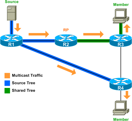
Consider the following topology:
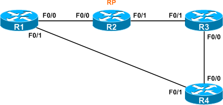
PIM-SM is enabled on all router interfaces, and R2's loopback address of 2.2.2.2 has been statically configured as the RP on all routers in the network, including R2 itself, with the ip pim rp-address command.
R2(config)# ip pim rp-address 2.2.2.2
With an RP established, we can observe what happens when a source begins to transmit multicast traffic.
Source Trees
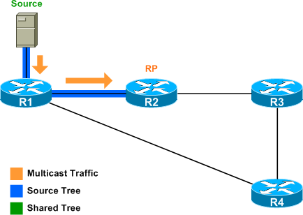
Assume a multicast server connected to R1 begins sending multicast traffic for group 239.1.2.3. When R1 receives this traffic, it recognizes it as destined for a multicast group because the destination IP address (239.1.2.3) resides in the 224.0.0.0/4 range. R1 automatically installs two routes in its multicast routing table:
R1# show ip mroute 239.1.2.3
IP Multicast Routing Table
Flags: D - Dense, S - Sparse, B - Bidir Group, s - SSM Group, C - Connected,
   L - Local, P - Pruned, R - RP-bit set, F - Register flag,
   T - SPT-bit set, J - Join SPT, M - MSDP created entry,
   X - Proxy Join Timer Running, A - Candidate for MSDP Advertisement,
   U - URD, I - Received Source Specific Host Report,
   Z - Multicast Tunnel, z - MDT-data group sender,
   Y - Joined MDT-data group, y - Sending to MDT-data group
Outgoing interface flags: H - Hardware switched, A - Assert winner
 Timers: Uptime/Expires
 Interface state: Interface, Next-Hop or VCD, State/Mode

(*, 239.1.2.3), 00:00:13/stopped, RP 2.2.2.2, flags: SPF
  Incoming interface: FastEthernet0/0, RPF nbr 10.0.12.2
  Outgoing interface list: Null

(192.168.1.100, 239.1.2.3), 00:00:13/00:02:58, flags: PFT
  Incoming interface: FastEthernet1/0, RPF nbr 0.0.0.0, Registering
  Outgoing interface list: Null
The (*, 239.1.2.3) route represents the a shared tree rooted at the RP (notice the incoming interface listed as FastEthernet0/0, from R2). This tree hasn't actually been built yet; think of the route as a placeholder. The (192.168.1.100, 239.1.2.3) route represents the source tree, rooted at the multicast source (from FastEthernet1/0).
R1 does not immediately begin forwarding the multicast traffic; note that the outgoing interface list (OIL) for both routes is null. Instead, R1 begins encapsulating multicast packets from the source into PIM register messages and forwards them toward the RP. Note that the register messages are addressed to the group (239.1.2.3), not to the RP itself.
When the RP receives the first register message, it creates its own entries for the two trees:
R2# show ip mroute 239.1.2.3

(*, 239.1.2.3), 00:03:56/stopped, RP 2.2.2.2, flags: SP
  Incoming interface: Null, RPF nbr 0.0.0.0
  Outgoing interface list: Null

(192.168.1.100, 239.1.2.3), 00:00:05/00:02:54, flags: P
  Incoming interface: FastEthernet0/0, RPF nbr 10.0.12.1
  Outgoing interface list: Null
Notice that the source tree is listed as incoming from R1, while the shared tree has no incoming interfaces, as it isn't built from the RP until at least one member has joined the group. Maintaining a source tree from the source to the RP ensures the RP knows the address of the multicast source(s) for the group.
After creating the two routes in its multicast routing table, the RP sends a register stop message to R1, informing it to stop sending register messages. The delay between register and register stop messages is typically only a fraction of a second.
Routes for both trees will remain in the tables of both routers as long as multicast traffic is being sent to the group. At this point, neither R3 nor R4 have any knowledge of the 239.1.2.3 group:
R3# show ip mroute 239.1.2.3
Group 239.1.2.3 not found
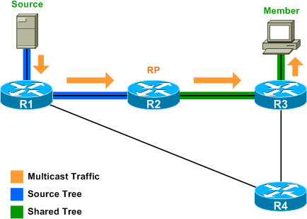
Shared Trees
Enter a group member on R3. The multicast client indicates to R3 it wants to receive traffic for the 239.1.2.3 group via IGMP. R3 annotates the IGMP join in its multicast routing table and sends a PIM join request for the group to the RP (R2). The RP receives the join request from R3, and adds FastEthernet0/1 (to R3) in the outgoing interface lists for both mroutes:
R2# show ip mroute 239.1.2.3

(*, 239.1.2.3), 00:00:30/00:03:17, RP 2.2.2.2, flags: S
  Incoming interface: Null, RPF nbr 0.0.0.0
  Outgoing interface list:
FastEthernet0/1, Forward/Sparse, 00:00:12/00:03:17

(192.168.1.100, 239.1.2.3), 00:00:30/00:03:23, flags: T
  Incoming interface: FastEthernet0/0, RPF nbr 10.0.12.1
  Outgoing interface list:
FastEthernet0/1, Forward/Sparse, 00:00:12/00:03:17
In this manner, the source and shared trees are joined. However, because the RP didn't previously have any outgoing interfaces for either tree, it issues its own join request up the source tree to R1, requesting that multicast traffic for the group be forwarded to the RP.
Upon receiving the RP's join request on the source tree, R1 removes the prune (P) flag from its (192.168.1.100, 239.1.2.3) mroute and adds FastEthernet0/0 (to R2) as an outgoing interface:
R1# show ip mroute 239.1.2.3

(*, 239.1.2.3), 00:00:33/stopped, RP 2.2.2.2, flags: SPF
  Incoming interface: FastEthernet0/0, RPF nbr 10.0.12.2
  Outgoing interface list: Null

(192.168.1.100, 239.1.2.3), 00:00:33/00:03:20, flags: FT
  Incoming interface: FastEthernet1/0, RPF nbr 0.0.0.0
  Outgoing interface list:
FastEthernet0/0, Forward/Sparse, 00:00:15/00:03:14
Multicast traffic is now flowing from the source on R1 to the group member on R3.
Compare the table of R1 (on the source tree) to that of R3 (on the shared tree):
R3# show ip mroute 239.1.2.3

(*, 239.1.2.3), 00:00:22/00:02:59, RP 2.2.2.2, flags: SCL
  Incoming interface: FastEthernet0/1, RPF nbr 10.0.23.2
  Outgoing interface list:
FastEthernet1/0, Forward/Sparse, 00:00:22/00:02:55
Notice that R3 has only a single route, (*, 239.1.2.3), for the shared tree rooted at the RP; it has no knowledge of the source tree between R1 and R2.
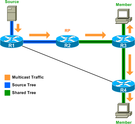
When additional members join the multicast group, the shared tree is simply extended through additional join requests between PIM routers:
R4# show ip mroute 239.1.2.3

(*, 239.1.2.3), 00:00:08/00:02:59, RP 2.2.2.2, flags: SCL
  Incoming interface: FastEthernet0/0, RPF nbr 10.0.34.3
  Outgoing interface list:
FastEthernet1/0, Forward/Sparse, 00:00:08/00:02:55
One final note: after Cisco PIM-SM routers have determined the source of multicast traffic for a group, they will by default switch over to a source tree in order to more efficiently forward traffic. For example, assuming all links have an equal cost, multicast traffic has a more favorable route to R4 via the direct link from R1. PIM is able to detect this by inspecting the unicast routing table, and R4 will switch over to a source tree by sending a PIM join request to R1:
R4# show ip mroute 239.1.2.3

(*, 239.1.2.3), 00:00:22/00:02:38, RP 2.2.2.2, flags: SJCL
  Incoming interface: FastEthernet0/0, RPF nbr 10.0.34.3
  Outgoing interface list:
FastEthernet1/0, Forward/Sparse, 00:00:22/00:02:37

(192.168.1.100, 239.1.2.3), 00:00:21/00:02:58, flags: LJT
  Incoming interface: FastEthernet0/1, RPF nbr 10.0.14.1
  Outgoing interface list:
FastEthernet1/0, Forward/Sparse, 00:00:21/00:02:38
This behavior can be disabled with the ip pim spt-threshold infinity command.
Posted in Multicast
Comments
October 21, 2008 at 12:42 p.m. UTC
Great article, thanks! Multicast has been one of those topics in the BSCI that has been of particular difficulty for me. This post has really cleared up some fundamental concepts and I think I'm starting to understand it a lot better. Keep em coming.
Just a note, there's a typo in the paragraph just above the last image "multicast traffic would [have] a more favorable route"
November 14, 2008 at 1:58 p.m. UTC
Well written, clear and concise. Selection of the RP router has been my point of confusion. This article cleared it up for me. Keep it up my friend. Good job.
December 29, 2008 at 5:38 a.m. UTC
Superb!!! Conceptual explanation is very clear. Had read a lot of Mcast material but this one was spot on!!
January 23, 2009 at 1:44 p.m. UTC
Very good read. Thanks
January 26, 2009 at 11:25 a.m. UTC
I've recently graduated from an internet design program and just found your site last week. Since then I've been going crazy combing through your articles and labs. Really good stuff, your writing is clear and your diagrams compliment it very well. This site has really helped me to refresh the material I learned in school and fill in some gaps that got left out.
Thank you for your excellent work and making it available to everyone.
Cheers, Greg
June 15, 2009 at 7:51 p.m. UTC
Wow!.. This is an excellent starting point for reviewing the basics of Multicast Routing...crystal clear. I will definitely recommend it on my blog. Thanks!
June 26, 2009 at 10:50 p.m. UTC
Thanks man. It has enabled me to understand the rudiments of PIM-SM.
July 10, 2009 at 5:55 p.m. UTC
after the shared to source switch over why do I SJC on ,G? Should it not be pruned? Not only am I seeing SJC for the ,G but I am seeing it stopped? What exactly does stop mean?
I'm working on a NGEN-MVPN design in my lab and see this behavior on all my Receiver CE's.
Any feedback is very appreciated.
-Chip
November 30, 2010 at 1:45 a.m. UTC
Great article. I'm having a hard time understanding multicast studying for CCIE Lab and this one definitely helps me get the ball rolling. Keep them coming.
Jason Wang
May 22, 2011 at 3:41 p.m. UTC
thanx a lot..u r a grt guy..i am a big fan of u..frm india
June 21, 2011 at 2:08 p.m. UTC
R3 has only a single route, (*, 239.1.2.3), for the shared tree rooted at the RP; it has no knowledge of the source tree between R1 and R2. When R4 joins the group, it is the same with R3, how it knows source tree ip and convert to source tree. Thanks
Yong
July 13, 2012 at 8:54 p.m. UTC
Great article and very well explained.
May 2, 2013 at 5:06 a.m. UTC
Very well written,one of the best articles written on multicast
May 15, 2013 at 8:46 a.m. UTC
Great composing and explanation.... U r an Angel ....Thanks for wonderful work..
June 19, 2013 at 5:53 p.m. UTC
its really very good explained. thank you a lot. Its really very easily written.
September 5, 2013 at 7:51 a.m. UTC
Amazing explanation ! Thank you
January 4, 2014 at 2:34 p.m. UTC
Wonderful. Emulated step by step and tested. Really is helpful.
June 3, 2014 at 8:59 p.m. UTC
I must have read chapters for three different books, watched various youtube videos when I finally came across this link. By far the best explanation of what happens with Sparse mode.Thank you!
July 3, 2014 at 10:05 a.m. UTC
I've got a problem when I test IPv6 PIM-SM. My topology is similar as yours. Then set F0/0 of R3 to join a mcast group, e.g. FF05::1234. Ping the mcast from loopback0 of R1 would get a reply from R3. However, ping mcast (or any other mcast packets) from "Source" will not be encapsulated to unicast. In R1, "show ipv6 moute" shows that the (S,G) is still in "Registering" status. Do you have any idea about this problem?
July 5, 2015 at 4:48 p.m. UTC
Well explained. Thanks for the article.
August 16, 2016 at 2:02 p.m. UTC
Thank you Jeremy for the write up. It is better to explain about FastEthernet1/0 you mentioned in the article since in the diagrams it is not mentioned.