The premiere source of truth powering network automation. Open and extensible, trusted by thousands.
NetBox is now available as a managed cloud solution! Stop worrying about your tooling and get back to building networks.
OSPF as a distance vector protocol
By stretch | Monday, October 13, 2008 at 2:04 a.m. UTC
Examine the OSPF topology below. Assuming all links have an equal cost, which path will R3 take to R5?
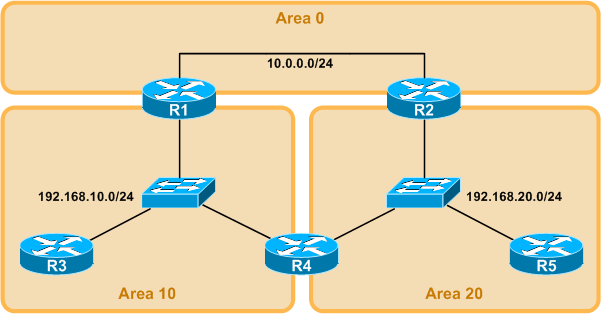
The obvious answer is the path through R4, as it is only two hops. However, the path that is actually taken is the one through R1 and R2 in area 0:
R3# traceroute 192.168.20.5

Type escape sequence to abort.
Tracing the route to 192.168.20.5

1 192.168.10.1 20 msec 12 msec 16 msec
  2 10.0.0.2 12 msec 24 msec 20 msec
  3 192.168.20.5 12 msec *  24 msec
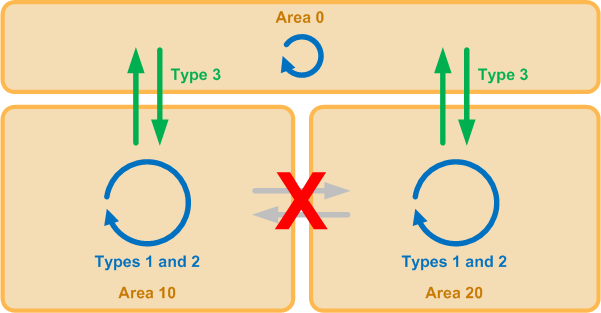
Why? Although OSPF operates as a link-state routing protocol within an area, its behavior between areas is predominantly distance vector. Link-state trees (formed from LSA types 1 and 2) are only maintained within an area; summary routes (type 3 LSAs) are used to statelessly transport routing information between areas. To prevent routing loops, areas must be connected in a logical star topology, centering around area 0. All type 3 LSAs must therefore pass into or out of area 0 when multiple areas are in use, whereas type 1 and 2 LSAs are confined to the local area.
We can better observe this limitation by examining R3's OSPF database:
R3# show ip ospf database

OSPF Router with ID (3.3.3.3) (Process ID 1)

Router Link States (Area 10)

Link ID         ADV Router      Age         Seq#       Checksum Link count
1.1.1.1         1.1.1.1         1006        0x80000002 0x00F244 1
3.3.3.3         3.3.3.3         1001        0x80000002 0x0073B2 1
4.4.4.4         4.4.4.4         965         0x80000002 0x0035E7 1

Net Link States (Area 10)

Link ID         ADV Router      Age         Seq#       Checksum
192.168.10.1    1.1.1.1         967         0x80000002 0x001F7D

Summary Net Link States (Area 10)

Link ID         ADV Router      Age         Seq#       Checksum
10.0.0.0        1.1.1.1         987         0x80000003 0x0049D9
192.168.20.0    1.1.1.1         888         0x80000001 0x00A502
Note that the summary LSAs are only being advertised from R1, because that is the only router in area 10 also connected to area 0. R4, although it belongs to both areas, will not propagate LSAs from one area to the other, as it has no access to area 0. If it were to pass summary routes, for example, from area 10 to area 20, those routes would then be passed along by R2 to area 0 and by R1 back into area 10, forming a routing loop. By forcing all area border routers (ABRs) to attach to the common link-state tree in area 0, such loops are avoided.
A good point to remember if you're ever being interviewed by Jeff Dyole.
Posted in Routing
Comments
October 13, 2008 at 3:37 p.m. UTC
Interesting post. I get it but I always thought that what made a DV protocol a DV protocol is the way that it learned routes: Distance = how far and Vector = what direction. All the information that it learns is from passing periodic updates of its routing table to its neighbors and vice-versa.
What made link state a link-state, I thought, was the fact that it passed Link-State packets rather than the entire routing table. However, taking a deeper look at how the ABR and summary routes play into this, it really makes sense.
Thanks Stretch!
October 13, 2008 at 4:38 p.m. UTC
Interviewed by Jeff Doyle. Mr. Routing TCP/IP Vol 1 & 2. I dread the though. I imagine it would be 2nd in intensity to being interviewed by John Cavanaugh.
October 13, 2008 at 5:06 p.m. UTC
Great writeup!
October 13, 2008 at 6:03 p.m. UTC
Great post.. I never really understood the difference between LSA types 1 vs 2 vs 3... This make more sense now. It would be a good thing to see the actual configuration for R1,R3,and R4 to see how the areas are defined on each router.
thank you
October 15, 2008 at 7:50 a.m. UTC
Your diagrams are A++ for their good looks and their high degree of user accessibility.
Sadly I got the answer wrong. Time to hit the books!
Love your work stretch.
October 15, 2008 at 10:25 a.m. UTC
Hi
I have a question concerning this setup. I did not yet manage to try this myself but what if you create a virtual link between R4 en area 0 (on both sides), Would it be possible to direct traffic via R4 between area 10 & 20?
Grt S
November 17, 2009 at 1:35 p.m. UTC
What's also interesting is that if the only path from R3 to R1 is through R4 the packet will travel the shortest path through R4 to R5 due to R4's routing table containg a route for R5.
These behaviors with weird OSPF topologies gave me endless headaches when first trying it out..
December 17, 2012 at 6:29 p.m. UTC
Great post! I just wanted to see if I got the challenge right.