The premiere source of truth powering network automation. Open and extensible, trusted by thousands.
NetBox is now available as a managed cloud solution! Stop worrying about your tooling and get back to building networks.
Visualizing tunnels
By stretch | Friday, July 11, 2008 at 11:08 a.m. UTC
When I was first introduced to tunnel interfaces, it took me a while to work out a solid visualization in my mind. Referencing documentation on the topic at the time probably would have sped things along considerably, but I digress. For the novice, I suggest thinking of a tunnel interface as simply adding or removing protocol headers, rather than transmitting packets. Consider the following illustration.
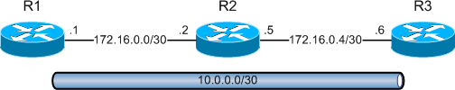
Routers 1, 2, and 3 are physically connected in series using point-to-point links in the 172.16.0.0/24 range. A tunnel between routers 1 and 3 is configured and addressed as 10.0.0.0/30. R1 has been configured to source the tunnel from its physical interface FastEthernet0/0, with the destination address of R3's 172.16.0.6 interface.
hostname R1
!
interface Tunnel0
 ip address 10.0.0.1 255.255.255.252
 tunnel source 172.16.0.1
 tunnel destination 172.16.0.6
!
interface FastEthernet0/0
 ip address 172.16.0.1 255.255.255.252
R3's configuration is a mirror image of R1:
hostname R3
!
interface Tunnel0
 ip address 10.0.0.2 255.255.255.252
 tunnel source 172.16.0.6
 tunnel destination 172.16.0.1
!
interface FastEthernet0/0
 ip address 172.16.0.6 255.255.255.252
R1 and R3 both view the 10.0.0.0/30 network as directly connected. Because we didn't specify a tunnel type in our setup, GRE encapsulation (the default mode) is used.
R1# show interface tun0
Tunnel0 is up, line protocol is up
  Hardware is Tunnel
  Internet address is 10.0.0.1/30
  MTU 1514 bytes, BW 9 Kbit, DLY 500000 usec,
 reliability 255/255, txload 1/255, rxload 1/255
  Encapsulation TUNNEL, loopback not set
  Keepalive not set
  Tunnel source 172.16.0.1, destination 172.16.0.6
  Tunnel protocol/transport GRE/IP
Key disabled, sequencing disabled
Checksumming of packets disabled
  Tunnel TTL 255
  Fast tunneling enabled
  ...
Although the tunnel terminates at a (virtual) interface, it isn't responsible for obtaining layer two adjacency information or for transmitting packets. Instead, packets routed into or out of a tunnel interface have a protocol header added or removed, respectively. Consider what happens when R1 receives a packet to be routed through the GRE tunnel.
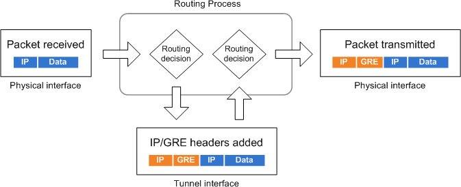
- A packet is received on or sourced from R1.
- A routing decision is made, and the packet is forwarded "out" the tunnel interface.
- The tunnel interface encapsulates the packet with a new IP header and a GRE header. Its destination IP address is that of the tunnel destination (172.16.0.6).
- A second routing decision is made to determine the new packet's outbound interface based on the outermost IP header.
- The packet is transmitted out the appropriate physical interface.
Having illustrated the outbound tunnel process, it's simple to reverse the flow and examine the inbound process.
- A packet is received on R3's physical interface.
- A routing decision determines that the destination address belongs to R3.
- The router recognizes the destination IP address and GRE header as belonging to the tunnel interface. The tunnel interface removes the outer IP and GRE headers, and the original IP packet is sent back "in" to the router.
- A second routing decision is performed based on the original destination IP address.
- The IP TTL is decremented by one and the packet is transmitted out the appropriate interface.
Note that R2 never sees packets destined to or from the 10.0.0.0/30 subnet, only for the tunnel endpoints 172.16.0.1 and 172.16.0.6. There are other, more interesting modes of tunnel encapsulation, such as IPv6-in-IP and IPsec, but the general flow remains the same.
Posted in Routing
Comments
July 11, 2008 at 12:04 p.m. UTC
You're so spot-on about this! I even remembered when I realized this myself, certainly over eight years ago. It's an eureka!-moment.
(btw. this makes me hate the way cisco ASA/FWSMs treats 'tunnels' with their crypto-maps).
July 11, 2008 at 1:37 p.m. UTC
Notice the default bandwidth on this tunnel is 9k! Might want to adjust that also for traffic flows...
July 11, 2008 at 3:45 p.m. UTC
Thanks! Another excellent article! Nice diagrams with good explanations. I enjoy checking your site daily for new installments! I have setup your GRE example in GNS3 and it worked a treat. Maybe you could do a simple IPsec example for people new to tunneling? Thanks again. Keep up the good work.
July 11, 2008 at 4:44 p.m. UTC
Thanks for the clear explanation! Where would this be most useful?
July 12, 2008 at 3:09 a.m. UTC
In most cases, GRE tunnels are used to carry multicast traffic. Example = dynamic routing protocols
There are several other uses as well that aren't coming to mind but I do recall reading about.
July 12, 2008 at 3:14 a.m. UTC
By the way, great site and articles! Your attention to detail is awesome and your study notes/guides are a big help.
July 14, 2008 at 1:37 p.m. UTC
@Paul: I expanded on this example to implement an IPsec tunnel in the post IPsec quick and dirty. Enjoy!
July 14, 2008 at 7:25 p.m. UTC
THNX...gr8 article...
I would also like to see (as Dirk-Jan van Helmond commented) the way how ASA/FWSMs treats 'tunnels' with their crypto-maps...TIA
July 23, 2008 at 5:03 a.m. UTC
Bingo! Easy as apple pie.. great piece of 'technical writing' :)
April 1, 2009 at 1:35 a.m. UTC
It's very helpful,thankyou!
December 30, 2009 at 12:55 a.m. UTC
Jeremy,
Say that you have other 10.0.0.0 networks attached to R1 and R3. Can these networks be advertised across the tunnel via dynamic routing protocols?
December 3, 2011 at 12:13 p.m. UTC
Excellent post Jeremy! Thank you.
July 23, 2013 at 3:43 a.m. UTC
Simple and clear, thanks Jeremy!
February 9, 2014 at 12:54 p.m. UTC
EXCELLENT MAN!
January 31, 2015 at 9:07 p.m. UTC
Nice article Jeremy. I have a couple of questions though:
How does the router determine WHEN to route traffic via the tunnel?
Other than seeing tunnel interface in an up up state, how can I verify that traffic is passing through the tunnel?
March 27, 2015 at 10:50 a.m. UTC
intresting and valuble
April 27, 2015 at 9:33 p.m. UTC
This taught me a lot! Great explanation. Thanks!
October 7, 2015 at 10:42 a.m. UTC
What is the need of giving tunnel a private IP address (10.0.0.1)when packets are to be routed using the destination IP address (172.16.0.6)?
June 17, 2016 at 7:13 p.m. UTC
http://www.cisco.com/c/en/us/td/docs/solutions/Enterprise/WAN_and_MAN/P2P_GRE_IPSec/P2P_GRE/2_p2pGRE_Phase2.html
"GRE also enables private addressing. Without a tunnel protocol running, all end stations are required to be addressed with registered IP addresses. By encapsulating the IP packet in a tunneling protocol, private address space can be used."
September 13, 2016 at 11:02 a.m. UTC
Thanks. SPOT on